

Method and device for enhancing magnetic disturbance based on gas injection to inhibit escape current
A gas injection and disturbance suppression technology, applied in the direction of reducing greenhouse gases, nuclear power generation, climate sustainability, etc., can solve problems such as the inability to reliably suppress escape current, and achieve the effect of enhancing transportation loss, ensuring safety, and avoiding damage.
- Summary
- Abstract
- Description
- Claims
- Application Information
AI Technical Summary
Problems solved by technology
Method used
Image

Examples
Embodiment 1
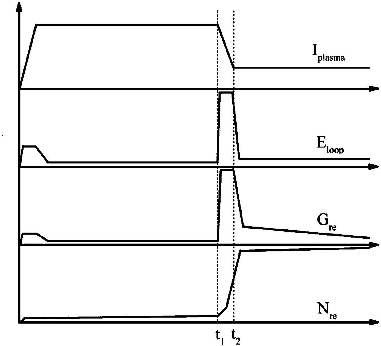
[0030] For this implementation, please refer to figure 1 , figure 2 and Figure 4 .
[0031] The method for suppressing escape current based on gas injection enhanced magnetic disturbance provided in this embodiment specifically includes the following steps:
[0032] 101. Install a gas injection device on the tokamak vacuum chamber so that the gas injection device is as close as possible to the plasma; specifically, in a specific implementation, there can be one or at least two gas injection devices, and the installation location can be in Any circumferential or polar position of the vacuum chamber. When more than two gas injection devices are provided, the gas injection devices are evenly installed at any circumferential or polar position of the vacuum chamber. The gas injection device is as close as possible to the plasma, which can reduce the distance of the gas from the gas injection device to the plasma, and shorten the time required to enhance the plasma magnetic dis...
Embodiment 2
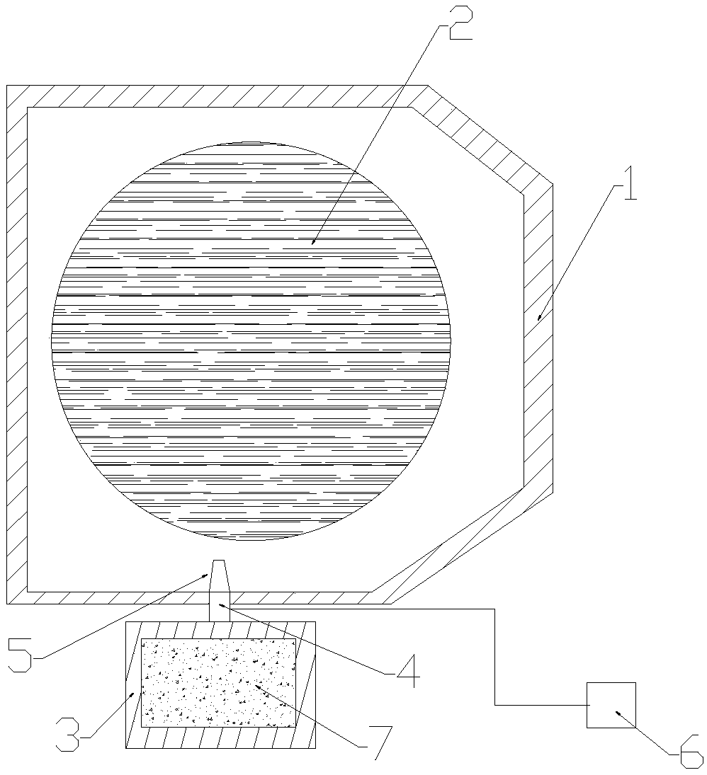
[0042] Please refer to image 3 , this embodiment provides a Tokamak gas injection device that realizes the method of enhancing magnetic disturbance and suppressing escape current based on gas 7 injection, the gas injection device includes a gas storage component 3, a switch valve 4, an injection nozzle 5, and a gas storage component 3 Located outside the vacuum chamber 1, the gas storage part 3 is as close as possible to the vacuum chamber to shorten the injection distance of the gas from the gas storage part 3 to the plasma 2, the injection nozzle 5 is located in the vacuum chamber, and the switch valve 4 is connected to the gas storage part 3 and the injection nozzle 5, and the trigger end of the switch valve 4 is connected to the tokamak central control system 6, the tokamak central control system 6 is the central control system of the existing tokamak device, the gas storage unit 3 Tokamak working gas 7 or inert gas 7 is stored in it; wherein, the gas injection device is ...
PUM
 Abstract
Description
Claims
Application Information