Supercharge Your Innovation With Domain-Expert AI Agents!

Uniformly-stressed forging device for environmental protection material production

An environmentally friendly material and uniform force technology, applied in forging/pressing/hammer devices, driving devices of forging presses, manufacturing tools, etc., can solve problems such as parts that do not meet standards, lower product qualification rates, and overall size deviations. To achieve the effect of improving pass rate, improving accuracy, improving forging quality and forging speed

Inactive Publication Date: 2018-07-20
合肥信比欣新材料有限公司
View PDF0 Cites 2 Cited by
  • Summary
  • Abstract
  • Description
  • Claims
  • Application Information

AI Technical Summary

Problems solved by technology

Among them, the relative rotary motion forging device includes a simple forging device. The specific structure of a simple forging device includes a main shaft, a heavy hammer is fixedly connected to the main shaft, a die is arranged under the heavy hammer, and a stepping motor is connected to the main shaft. , the stepping motor controls the spindle to rotate reciprocally, the spindle drives the heavy hammer to rotate reciprocally, and continuously forges the blank in the die. This kind of forging equipment makes the heavy hammer directly contact with the blank, because the heavy hammer moves in an arc, so it is very It is difficult to ensure that the force of hitting the billet is vertically downward every time. It often happens that the direction of the force of the heavy hammer hitting the billet is obliquely downward. The offset will eventually cause the overall size of the forged parts to deviate, causing the size of some parts to fail to meet the standard, reducing the qualified rate of the product

Method used


Image

  • Uniformly-stressed forging device for environmental protection material production
  • Uniformly-stressed forging device for environmental protection material production

Examples


Embodiment Construction

[0014] The technical solutions in the embodiments of the present invention will be clearly and completely described below with reference to the accompanying drawings in the embodiments of the present invention. Obviously, the described embodiments are only a part of the embodiments of the present invention, but not all of the embodiments. Based on the embodiments of the present invention, all other embodiments obtained by those of ordinary skill in the art without creative efforts shall fall within the protection scope of the present invention.

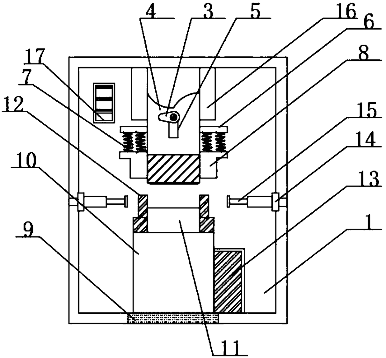
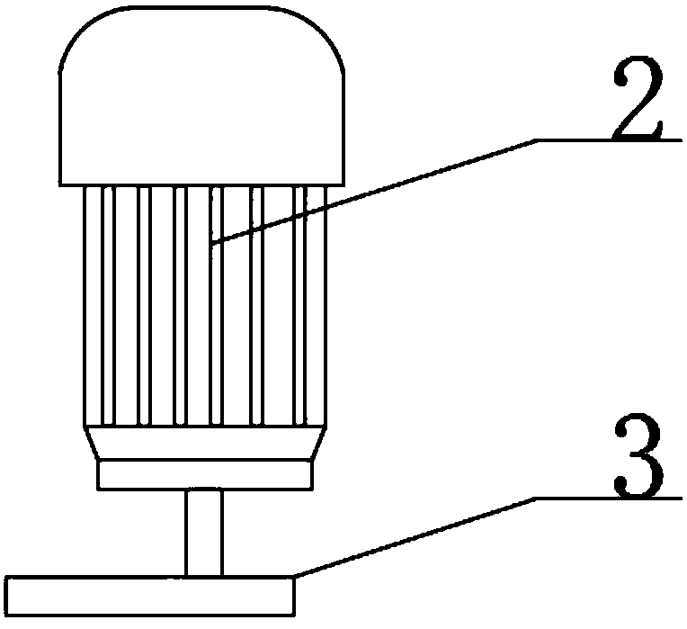
[0015] The present invention provides such as Figure 1-2 The shown forging device for producing environmentally friendly materials with uniform force includes a support table 1, a motor 2 is arranged on one side of the support table 1, and a cam 3 is arranged on the output shaft of the motor 2, and the cam 3 is arranged on the Forging the middle part of the upper die 4, the middle part of the upper forging die 4 is provided with a sl...


PUM


Abstract

The invention discloses a uniformly-stressed forging device for environmental protection material production. The uniformly-stressed forging device for environmental protection material production comprises a support table, wherein a motor is arranged on one side of the support table; a cam is arranged on an output shaft of the motor and is arranged in the middle of a forging upper die; fixing rods are arranged on sides of the forging upper die; compression springs are arranged on the bottom parts of the fixing rods; sliding plates are arranged on the bottom parts of the compression springs; aforging lower die is arranged on the top part of the support plate; hydraulic push rods are arranged on sides of the forging lower die; a hydraulic air cylinder is arranged on one side of the supportplate; electric rolling wheels are arranged on sides of the support table; and electric push rods are arranged at one ends of the electric rolling wheels. According to the uniformly-stressed forgingdevice for environmental protection material production provided by the invention, the cam is arranged in the middle of the forging upper die, and the forging upper die applies a vertical downward pressure on a blank, so that the sizes of forged parts can meet the standards, and the product acceptability is improved.

Description

technical field [0001] The invention relates to the field of forging devices, in particular to a forging device for producing environment-friendly materials with uniform force. Background technique [0002] Forging is a processing method that uses a forging machine to apply pressure to a metal blank to produce plastic deformation to obtain a forging with certain mechanical properties, certain shape and size. Therefore, a forging device for the production of environmentally friendly materials with uniform force is invented to solve The above problems are very necessary. There are many types of forging equipment. According to the different operation modes of the working parts, forging equipment can be divided into two categories: linear reciprocating motion and relative rotational motion. The relative rotary motion type forging device includes a simple forging device. The specific structure of the simple forging device includes a main shaft, a heavy hammer is fixedly connected...

Claims


Application Information

Patent Timeline
IPC IPC(8): B21J9/18B21J9/20B21J13/02B21J13/10B21J13/12
CPCB21J9/18B21J9/20B21J13/02B21J13/10B21J13/12
Inventor 许姗姗
Owner 合肥信比欣新材料有限公司
Features
  • R&D
  • Intellectual Property
  • Life Sciences
  • Materials
  • Tech Scout
  • Unparalleled Data Quality
  • Higher Quality Content
  • 60% Fewer Hallucinations
Learn More