
Tab laser cutting device and cutting block assembly thereof

A technology of laser cutting and block components, applied in laser welding equipment, welding equipment, metal processing equipment and other directions, can solve the problems of poor collection, waste of pole piece material, low material utilization rate, etc., to facilitate absorption and reduce material costs Effect

Pending Publication Date: 2018-07-20
GEESUN AUTOMATION TECH
View PDF0 Cites 0 Cited by
  • Summary
  • Abstract
  • Description
  • Claims
  • Application Information

AI Technical Summary

Problems solved by technology

[0002] After the pole piece is laser cut, the lug part is kept, and the waste part is discarded. If there is no waste edge, the cut waste will fall scattered and difficult to collect, which will cause serious damage to the laser cutting pole piece and other work. Therefore, the existing laser-cut pole pieces all have scrap edges, that is, the width of the pole piece raw material is 16-10mm wider than the finished product after cutting (8-10mm wide on one side)
After laser cutting the pole lug, the excess edge material connects the remaining scrap of the pole lug to ensure the waste is continuous and uninterrupted, which facilitates the collection of waste, and also ensures the stable and continuous cutting of the pole piece, but this method reduces the cost of the pole piece. Material utilization, a large amount of pole piece material is wasted
[0003] The existing methods of cutting tabs include flat cutting and roller cutting, but there are scraps connected to the tab waste, resulting in low material utilization, high cost, and serious waste of pole piece materials

Method used


Image

  • Tab laser cutting device and cutting block assembly thereof
  • Tab laser cutting device and cutting block assembly thereof
  • Tab laser cutting device and cutting block assembly thereof

Examples


Embodiment 1

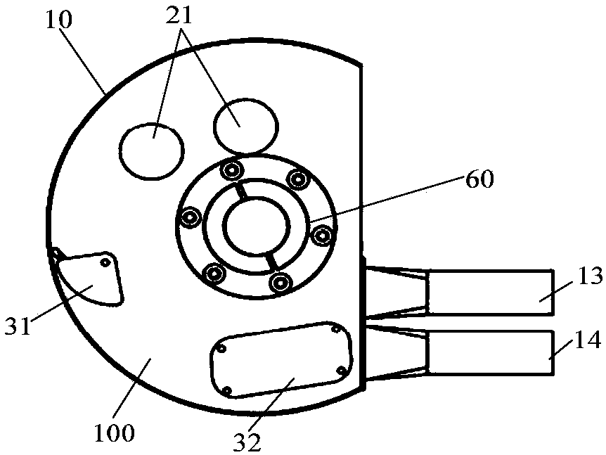
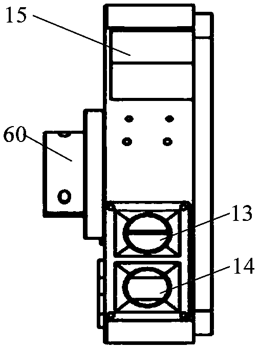
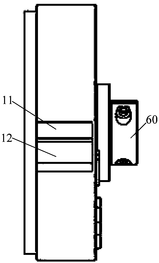
[0040] This embodiment provides a cutting block assembly of a laser tab cutting device, specifically a cutting block assembly for roll cutting. see Figure 1-Figure 4 As shown, the cutting block assembly includes a housing 100, the front of the housing 100 is provided with an arc-shaped support plate 10 for supporting the pole piece, and the support plate 10 is provided with a cutting opening 11 for laser cutting the pole lug and a Waste inlet 12 for collecting waste. Such as Figure 4 As shown, the interior of the housing 100 is configured as two independent cavity structures, namely a dust chamber 20 and a waste material chamber 30 ; the back of the housing 100 is provided with a dust outlet 13 and a waste material outlet 14 . Wherein, both the waste material inlet 12 and the waste material outlet 14 are connected to the waste material chamber 30 , and the cutting opening 11 and the dust outlet 13 are both connected to the dust chamber 20 . In this embodiment, the support...

Embodiment 2

[0048] This embodiment provides a laser tab cutting device, including the cutting block assembly described in the first embodiment. Since all the functions and features of the cutting block assembly are described in detail in the first embodiment, they will not be repeated here.

[0049] see Figure 13 and Figure 14 As shown, in this embodiment, the laser lug cutting device further includes: a first bracket 51, a second bracket 52, a first pressing block 53, a second pressing block 54, a roller 55, a first bearing 56, a second bearing 57, spacer sleeve 58 and roller shaft 59 etc.; The roller 55 is rotatably installed on the roller shaft 59, one end of the roller shaft 59 is installed on the first bracket 51, and the other end is installed on the second bracket 52; the first pressing block 53 is installed on the first bracket 51 To compress one end of the passing roller shaft 59, the second pressing block 54 is installed on the second bracket 52 to compress the other end of ...


PUM


Abstract

The invention discloses a tab laser cutting device and a cutting block assembly thereof. The cutting block assembly of the tab laser cutting device comprises a shell. A supporting plate for supportinga pole piece is arranged on the front side of the shell and is in the shape of an arc. A cutting port and a waste material inlet are formed in the supporting plate. A dust chamber and a waste material chamber are formed in the shell. A dust outlet and a waste material outlet are formed in the shell. Both the waste material inlet and the waste material outlet communicate with the waste material chamber. Both the cutting port and the dust outlet communicate with the dust chamber. The cutting block assembly absorbs the advantages of rolling slitting, the cutting, without waste material edges, onpole pieces is realized, the material cost is reduced, and waste materials can be sucked conveniently.

Description

technical field [0001] The present application relates to the field of lithium ion battery production equipment, in particular to a laser tab cutting device and a cutting block assembly thereof. Background technique [0002] After the pole piece is laser cut, the lug part is kept, and the waste part is discarded. If there is no waste edge, the cut waste will fall scattered and difficult to collect, which will cause serious damage to the laser cutting pole piece and other work. Influence, therefore, existing laser cutting pole piece all has scrap edge, promptly the pole piece raw material width is wider than the finished product after cutting 16-10mm (unilateral width 8-10mm). After laser cutting the pole lug, the excess edge material connects the remaining scrap of the pole lug to ensure the waste is continuous and uninterrupted, which facilitates the collection of waste, and also ensures the stable and continuous cutting of the pole piece, but this method reduces the cost o...

Claims


Application Information

Patent Timeline
Patent Type & Authority Applications(China)
IPC IPC(8): B23K26/38B23K26/70
CPCB23K26/38B23K26/70B23K26/702
Inventor 雷杰陈荣军吴学科陈强阳如坤
Owner GEESUN AUTOMATION TECH
Learn More