Deflection type plane polishing device with wear compensation

A wear compensation and polishing device technology, applied in grinding/polishing safety devices, grinding/polishing equipment, optical surface grinders, etc., can solve the problem of uneven polishing pressure on the processing surface of components, deterioration of the intermediate frequency index of components, and the distribution of processing surface shapes. Poor consistency and other problems, to avoid the reduction of component processing accuracy, reduce uneven stress, and avoid uncontrollable surface distribution

Pending Publication Date: 2018-07-20
成都精密光学工程研究中心
View PDF10 Cites 3 Cited by
  • Summary
  • Abstract
  • Description
  • Claims
  • Application Information

AI Technical Summary

Problems solved by technology

However, this technology relies more on the experience of the processing personnel, indirectly controls the overall surface shape of the component through the correction and control of the overall surface shape of the disk surface, and controls the surface shape distribution of the edge of the component through the adjustment of the exposed edge amount of the component. Carry out multiple measurements until the final index requirements are met, overall time-consuming and low processing efficiency
[0003] And in the traditional processing method, the component to be processed is placed directly on the surface of the polishing disc. Due to the elastic deformation of the polishing disc surface, the force on the corner of the large-diameter component will be higher than that in the middle area, resulting in the slump effect of the component; The local wear of the polishing disc surface will lead to the destruction of the surface shape of the polishing disc surface, resulting in uneven polishing pressure on the component processing surface, affecting the final processing surface shape accuracy of the component, and the processing surface shape distribution of the component is relatively poor; due to the component Periodic rotation movement at the same position, and periodic grooves on the polishing disc will produce obvious periodic ring marks on the surface of the component, resulting in deterioration of the intermediate frequency index of the component and seriously affecting the surface shape accuracy of the component

Method used


Image

  • Deflection type plane polishing device with wear compensation
  • Deflection type plane polishing device with wear compensation
  • Deflection type plane polishing device with wear compensation

Examples


Embodiment Construction

[0022] The following will clearly and completely describe the technical solutions in the embodiments of the present invention with reference to the accompanying drawings in the embodiments of the present invention. Obviously, the described embodiments are only some, not all, embodiments of the present invention. Based on the embodiments of the present invention, all other embodiments obtained by persons of ordinary skill in the art without making creative efforts belong to the protection scope of the present invention.

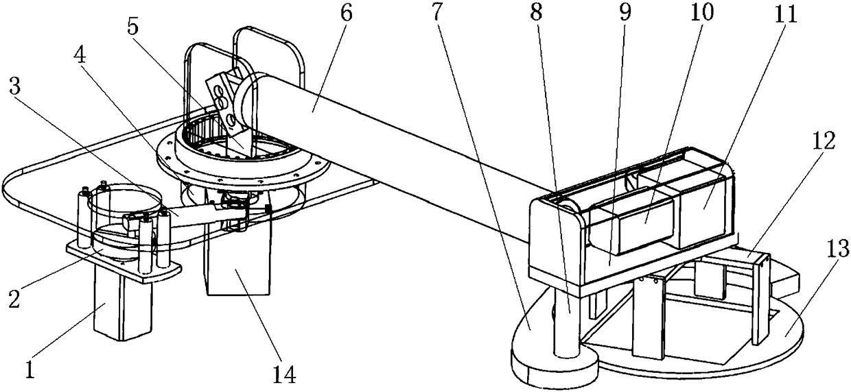
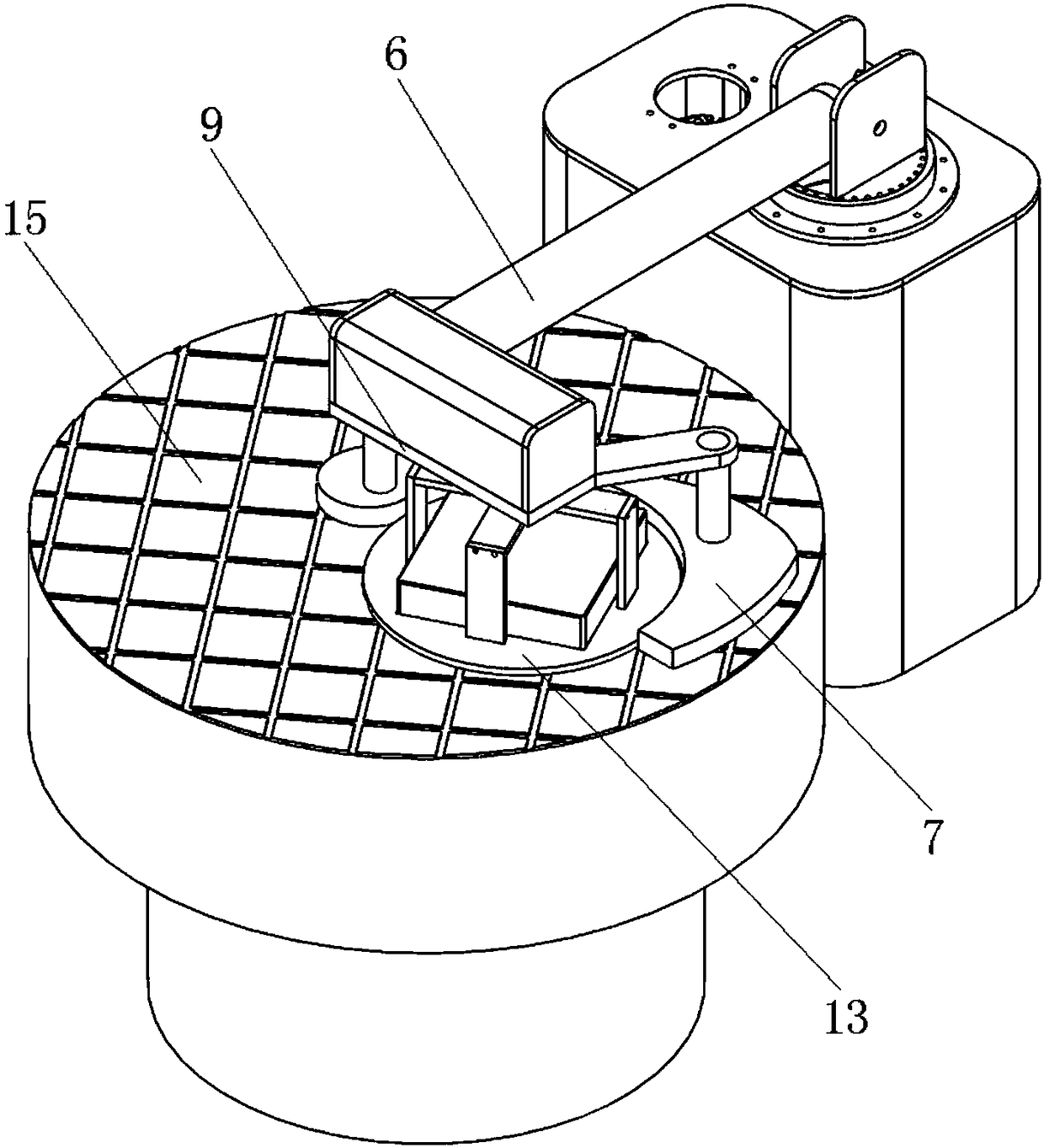
[0023] An oscillating plane polishing device with wear compensation disclosed in the embodiment of the present invention, the element performs a small oscillating movement while performing ring polishing, which suppresses the generation of ring marks on the processing element, and by placing the cage against the surface of the polishing disc Pressure loading is carried out to avoid edge slump of components, and the uneven wear of the radial position of the poli...


PUM


Abstract

The invention discloses a deflection type plane polishing device with wear compensation. The deflection type plane polishing device with wear compensation comprises a holder used for containing an element and an annular polishing drive mechanism; the holder is used for carrying out pressure loading on the polishing disc face, and enables the element to be attached to the polishing disc face, the annular polishing drive mechanism drives the holder to rotate on the polishing disc face so as to enable the element to be subject to annular polishing machining, a deflection mechanism capable of driving the holder to carry out deflection motion along the polishing disc face is arranged, a polishing disc wear compensation block attached to the polishing disc face is arranged on the periphery of the holder. The element is subject to deflection polishing while being subject to annular polishing, annular marks of the element can be effectively restrained, the polishing disc wear compensation block is used for compensating force uneven wear of the polishing disc face in the radial direction, the face form long-term stability of the polishing disc face is kept, the element machining precision and face form consistency are improved, the holder is used for carrying out pressure loading on the polishing disc, uneven stress of the element edge can be reduced, and element side collapsing and corner collapsing can be avoided.

Description

technical field [0001] The invention relates to the technical field of polishing processing equipment, in particular to an eccentric plane polishing device with wear compensation. Background technique [0002] The traditional polishing method for large-aperture planar reflective components is to use full-aperture continuous polishing technology to control the reflected wavefront of the component by controlling the overall disk shape and the exposed edge of the component. However, this technology relies more on the experience of the processing personnel, indirectly controls the overall surface shape of the component through the correction and control of the overall surface shape of the disk surface, and controls the surface shape distribution of the edge of the component through the adjustment of the exposed edge amount of the component. It takes a long time to perform multiple measurements until the final index requirements are met, and the processing efficiency is low. [...

Claims


Application Information

Patent Timeline
Patent Type & Authority Applications(China)
IPC IPC(8): B24B13/00B24B41/00B24B55/00
CPCB24B13/0018B24B41/007B24B55/00
Inventor 何祥谢磊黄颖黄金勇蔡超胡庆王刚赵恒鄢定尧马平
Owner 成都精密光学工程研究中心
Why Eureka
Try Eureka