
Vehicle-mounted road slope estimating device and method under full working conditions

A technology for all working conditions and slopes, applied to control devices, vehicle components, transportation and packaging, etc., can solve the problems of large influence, poor estimation effect, and inability to solve the influence of the slope estimation environment in turning conditions, etc.

Active Publication Date: 2018-07-20
CHINA FIRST AUTOMOBILE
View PDF11 Cites 21 Cited by
  • Summary
  • Abstract
  • Description
  • Claims
  • Application Information

AI Technical Summary

Problems solved by technology

[0005] (1) The influence of the dynamic change of the suspension cannot be eliminated. Since the input signal acceleration sensor is installed on the frame, the actual estimation is the attitude angle of the vehicle chassis, which is greatly affected by the attitude of the vehicle chassis
Therefore, in acceleration and deceleration conditions and off-road conditions, the estimation effect is poor
[0006] (2) Under turning conditions, due to the existence of the side slip angle of the center of mass, the measurement direction of the acceleration sensor is different from the direction of the vehicle speed, resulting in the measurement of the acceleration sensor is not the actual driving acceleration of the vehicle, which will also seriously affect the accuracy of slope estimation
[0008] (1) The signal of the longitudinal acceleration sensor used will also be affected by the attitude of the suspension;
[0009] (2) Road resistance will significantly affect the estimation results, so the estimation error is relatively large in off-road environments, especially in sandy, snowy and other road conditions;
[0010] (3) In turning conditions, the side slip angle of the center of mass also affects the accuracy of slope estimation
[0011] That is, the existing real-time road slope estimation methods cannot eliminate the error caused by the suspension attitude to the slope estimation, nor can it solve the slope estimation of the turning condition and even be affected by the environment
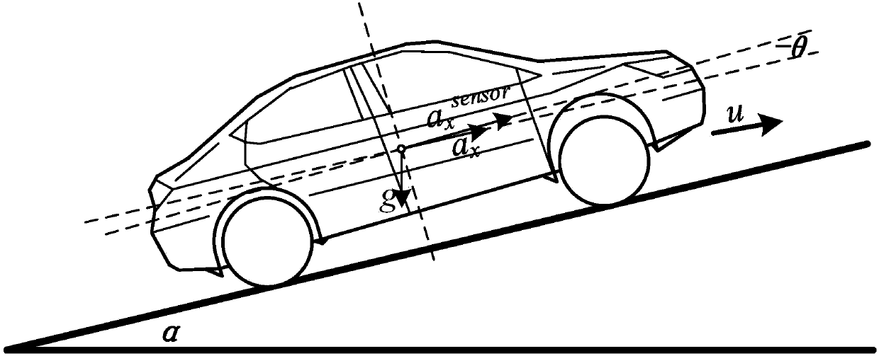
In the test, it was found that for an off-road vehicle with a wheelbase of 3m, the front and rear suspension difference would exceed 0.2m during the dynamic process of the vehicle, resulting in a suspension attitude error of about 6.7°, which would directly affect the slope estimation accuracy; while the road surface The rolling resistance coefficient also varies greatly on different road surfaces
Therefore, the existing methods are difficult to apply to all working conditions during vehicle driving

Method used


Image

  • Vehicle-mounted road slope estimating device and method under full working conditions
  • Vehicle-mounted road slope estimating device and method under full working conditions
  • Vehicle-mounted road slope estimating device and method under full working conditions

Examples


Embodiment 1

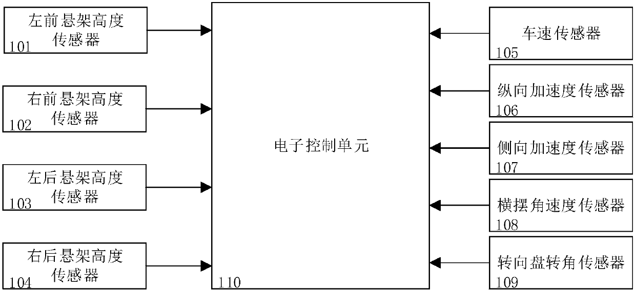
[0090] This embodiment provides a vehicle-mounted road gradient estimation device under all working conditions, which includes a left front suspension height sensor 101 installed on the left front suspension, a right front suspension height sensor 102 installed on the right front suspension, and a left rear suspension height sensor 102 installed on the left rear suspension. The left rear suspension height sensor 103 on the suspension, the right rear suspension height sensor 104 installed on the right rear suspension, the vehicle speed sensor 105 arranged on the chassis controller, and the longitudinal arrangement arranged at the vehicle center of mass position on the vehicle body A longitudinal acceleration sensor 106, a lateral acceleration sensor 107 arranged laterally at the position of the vehicle's center of mass on the body, a yaw rate sensor 108 disposed at the position of the vehicle's center of mass on the body, and a steering wheel angle sensor disposed on the steering...

Embodiment 2

[0103] This embodiment provides a method for estimating the slope of a road surface under all working conditions, which includes:

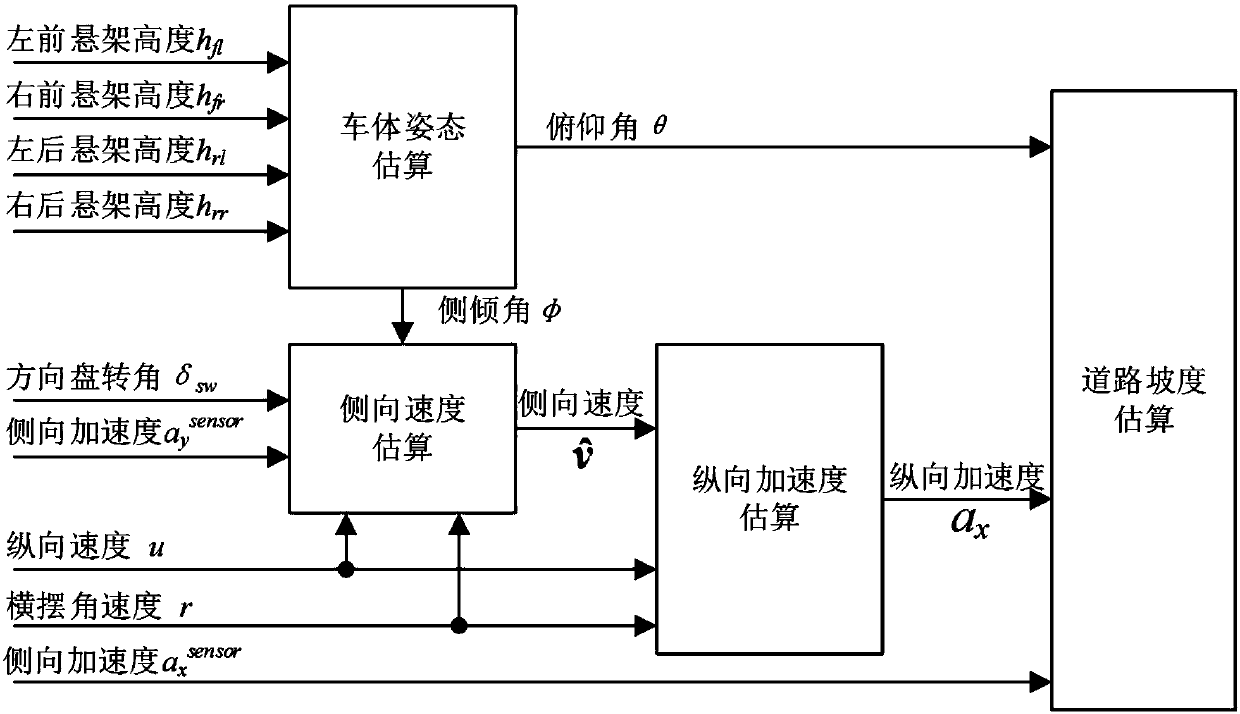
[0104] S10. Car Body Attitude Estimation

[0105] In this embodiment, the vehicle body attitude estimation specifically includes:

[0106] S101. Obtain the height signal h of the left front suspension through the left front suspension sensor 101 fl ; Obtain the right front suspension height signal h through the right front suspension sensor 102 fr ; Gather the left rear suspension height signal h by the left rear suspension sensor 103 rl ; Gather the right rear suspension height signal h through the right rear suspension sensor 104 rr .

[0107] S102. According to the left front suspension height signal h fl , right front suspension height signal h fr , left rear suspension height signal h rl and right rear suspension height signal h rr Calculate roll angle φ and pitch angle θ;

[0108] Specifically, during the operation of the vehicle, t...


PUM


Abstract

The invention discloses a vehicle-mounted road slope estimating device and method under full working conditions. In order to estimate the road slope in the process of the driving of a vehicle, a suspension height signal, a longitudinal speed signal, a longitudinal acceleration signal, a lateral acceleration signal, a yaw angular velocity signal and a steering-wheel steering-angle of the vehicle are collected, and the influence of a vehicle body attitude and the lateral motion of the vehicle on the using of an acceleration gravity component estimation method is considered. Compared with an existing method, the estimation error caused by the vehicle body attitude and the calculation of the actual longitudinal acceleration can be eliminated; and even if the vehicle is in the dynamic working conditions, such as rapid change of the longitudinal acceleration and violent steering, or even if the vehicle is on the high-slope road surface, the method has good estimation precision, and can adaptto the various working conditions of the normal vehicle running.

Description

technical field [0001] The invention belongs to the technical field of automotive electronics, and in particular relates to a vehicle-mounted road slope estimation device and method under all working conditions. Background technique [0002] With the development of intelligence and integration of automotive electronic control systems, the functions of electronic control systems are becoming more and more complex, and more and more vehicle status and road information are required. The real-time road slope is a very important piece of road information, which is of great significance for improving the intelligence and informatization of automobiles. For example, it is very important for speed control compensation, navigation information assistance, vehicle safety and handling stability control of smart cars; for off-road vehicles, slope information has a great impact on driving safety when driving in off-road environments. The control system also needs to perform compensation ...

Claims


Application Information

Patent Timeline
IPC IPC(8): B60W40/076
CPCB60W40/076B60W2520/125B60W2510/22B60W2520/105B60W2520/10B60W2540/18B60W2552/15
Inventor 张建王御刘秋铮刘晔王康李超彭晓宇李素文
Owner CHINA FIRST AUTOMOBILE
Learn More