Connecting structure of fabricated concrete-filled steel tubular column body

A technology of steel pipe concrete and connection structures, applied in the direction of columns, pillars, pier columns, etc., can solve the problems of difficult quality of concrete pouring, weak bonding between cementing materials and concrete, unfavorable construction quality of connection parts, etc., and achieve good ductility and energy dissipation capacity, shorten the concrete transportation distance, and avoid the effect of concrete quality damage

Active Publication Date: 2018-07-20
重庆大学建筑规划设计研究总院有限公司
View PDF12 Cites 18 Cited by
  • Summary
  • Abstract
  • Description
  • Claims
  • Application Information

AI Technical Summary

Problems solved by technology

[0005] The existing problems of the connection structure of this steel pipe concrete column are: the concrete is poured on site, the quality of the concrete pouring is difficult to guarantee, and these processes cause serious environmental pollution (such as dust, noise, etc.), which does not meet the national energy conservation and emission reduction requirements. related policy
[0007] The disadvantages of this patent are: 1. Since the upper and lower columns are prefabricated, many butt joints of steel bars are reserved, which requires a high level of component prefabrication, complicated on-site splicing, low assembly efficiency, and is not conducive to improving the connection. The construction quality of the site; 2. The steel pipe junction is a weak shearing surface, and the bonding effect between the cementing material and the concrete is weak. The outer steel pipe is resistant to shearing, which poses a safety hazard to the structure

Method used


Image

  • Connecting structure of fabricated concrete-filled steel tubular column body
  • Connecting structure of fabricated concrete-filled steel tubular column body
  • Connecting structure of fabricated concrete-filled steel tubular column body

Examples


Embodiment Construction

[0028] Below in conjunction with accompanying drawing and embodiment the present invention will be further described:

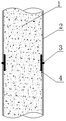
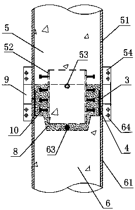
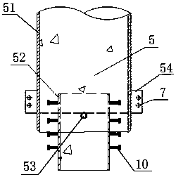
[0029] Such as figure 2 , image 3 and Figure 4 As shown, the present invention includes a first steel pipe column section 5 and a second steel pipe column section 6;

[0030] Such as image 3 As shown, the first steel pipe column section 5 includes a first outer steel pipe 51 filled with concrete. The inner steel pipe 52 full of concrete, the outer ring of the inner steel pipe 52 is equipped with screws 10 to enhance the fitting force, and the first outer steel pipe 51 has a vent hole 53 on the hollow section wall, and the vent hole 53 discharges the air in the gap area, the first The outer wall of the port of the outer steel pipe 51 is welded with a first ear plate 54 with a connecting hole 7, and the exhaust hole 53 and the first ear plate 54 are arranged in a staggered manner along the outer circumference of the first outer steel pipe 51;

[0031] ...


PUM


Abstract

The invention discloses a connecting structure of a fabricated concrete-filled steel tubular column body. The connecting structure comprises a first steel tubular column section and a second steel tubular column section; the first steel tubular column section is in butt joint with the second steel tubular column section, an inner steel tube is inserted into an inserting groove in a second outer steel tube, and a liner tube is arranged at the connecting position of a first outer steel tube and the second outer steel tube; the first outer steel tube, the second outer steel tube and the liner tube are welded into one through V-shaped groove welding; cementing materials are poured into gap areas in the first outer steel tube and the second outer steel tube, and air in the gap areas is exhausted though exhaust vents; and connecting plates are mounted on a first lug plate and a second lug plate through bolts. The connecting structure has the advantages that the shear-bearing ability of the connecting parts is improved, so that the column body reaches the normal section compression-bending bearing force and the shear-bearing ability which are not less than those of cast-in-place concrete,mounting is easy and convenient, the production and construction efficiency is improved, dust and noise pollution is further reduced, and the environmental-friendly requirements of green buildings are met.

Description

technical field [0001] The invention belongs to the technical field of structural engineering, and in particular relates to a connection between upper and lower steel pipe concrete columns. Background technique [0002] With the rapid development of my country's economic construction, the construction process of the traditionally used reinforced concrete structure is very serious to the environment, which is no longer in line with the "applicable, economical, green and beautiful" architectural policy promoted by the state. The prefabricated building structure has the characteristics of energy saving and environmental protection, and complies with the requirements of the era of green buildings. In addition, the prefabricated assembly structure is prefabricated in the factory, which can realize the factory production of prefabricated components and assemble them on the construction site. The construction process on the construction site saves the process of concrete pouring ma...

Claims


Application Information

Patent Timeline
Patent Type & Authority Applications(China)
IPC IPC(8): E04C3/34E04B1/58
CPCE04B1/585E04C3/34
Inventor 杨红孙攀旭罗洋郭超王志军
Owner 重庆大学建筑规划设计研究总院有限公司
Why Eureka
Try Eureka