Wall surface shoveling machine

A technology of wall skin and telescopic mechanism, which is applied in the direction of building maintenance, construction, building construction, etc., can solve the problems of time-consuming and labor-intensive, low efficiency of manual cleaning, and difficulty in meeting people's decoration needs, so as to expand the working area, facilitate the collection of waste, The effect of improving efficiency

Inactive Publication Date: 2018-07-20
欧新颖
0 Cites 23 Cited by

AI-Extracted Technical Summary

Problems solved by technology

It integrates modern science and technology with culture and art, and has close ties with architectural design, geography, decorative arts, ergonomics, psychology, aesthetics, science and technology materials, etc. In recent years, the construction industry has developed ver...

Abstract

The invention discloses a wall surface shoveling machine comprising a base, universal wheels, a slide block, a collecting box and a push rod, wherein a slide rail is fixedly connected on the upper surface of the base, and a forward and reverse rotating motor is fixedly connected on the lower surface of the base. A screw rod is fixedly connected to the shaft extension end of the forward and reverserotating motor, the screw rod is sleeved with the slide block, a first fixing frame is arranged below a spray head, and a driving shaft is arranged inside the first fixing frame. A sliding plate is arranged on the right end of the first fixing frame, a rack is fixedly connected to the left side wall of the sliding plate, and scrapers are distributed on the right side wall of the sliding plate. Awater pump is used for spraying water in a water tank on the surface of a wall, the surface of the wall is wet, and shoveling work is facilitated. In the working process, the scrapers move up and downalong the surface of the wall to shovel the wall surface. Each scraper consists of upper and lower blades, the efficiency of shoveling the wall surface is greatly improved, the amount of labor of workers is reduced, the slide block is driven to move up and down by using the forward and reverse rotating motor, and the operation area is enlarged. A smoothing roller is used for smoothing the surfaceof the wall after wall surface shoveling.

Application Domain

Technology Topic

Image

  • Wall surface shoveling machine
  • Wall surface shoveling machine
  • Wall surface shoveling machine

Examples

  • Experimental program(1)

Example Embodiment

[0017] The technical solutions in the embodiments of the present invention will be clearly and completely described below in conjunction with the accompanying drawings in the embodiments of the present invention. Obviously, the described embodiments are only a part of the embodiments of the present invention, rather than all the embodiments. Based on the embodiments of the present invention, all other embodiments obtained by those of ordinary skill in the art without creative work shall fall within the protection scope of the present invention.
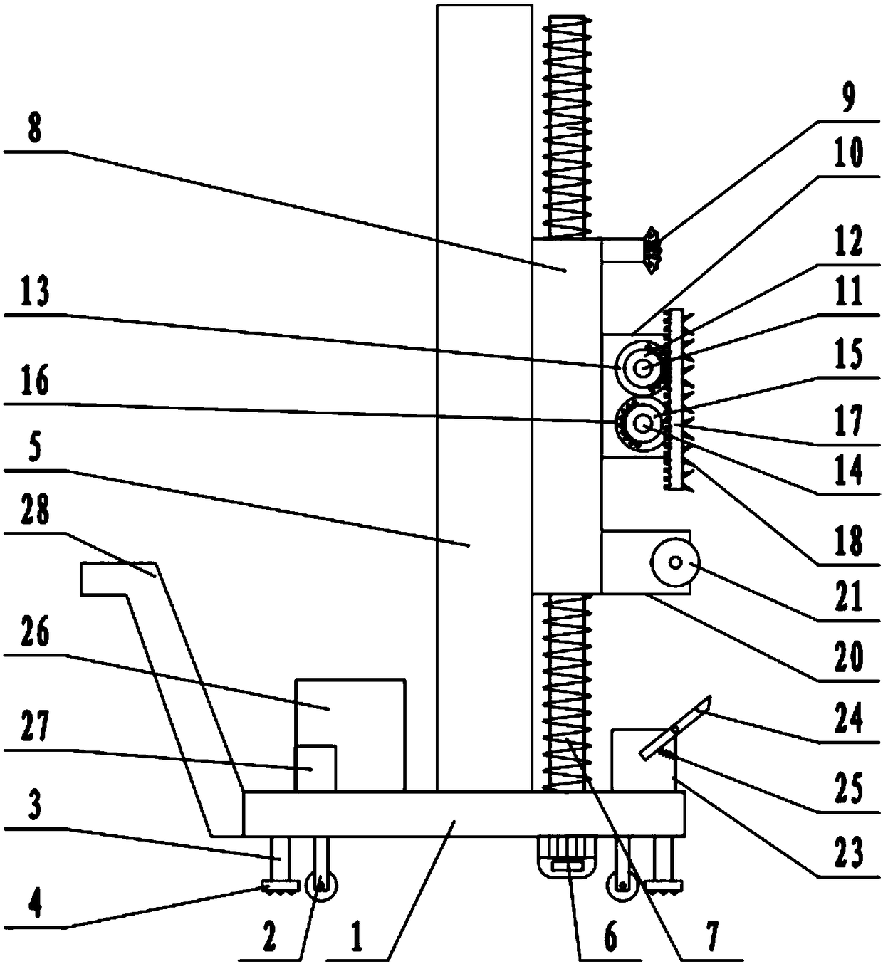
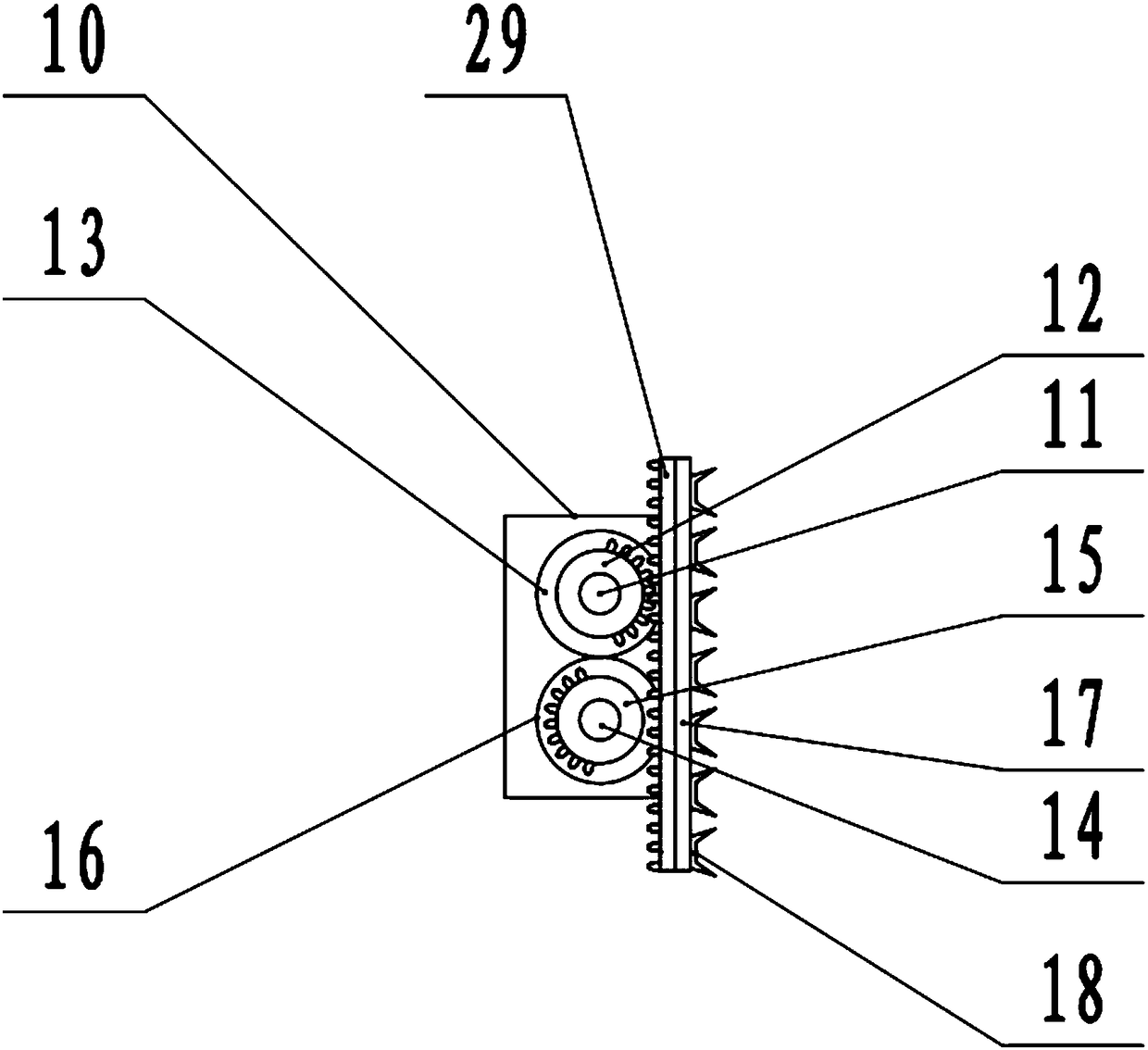
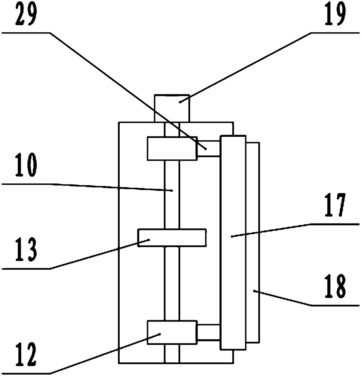
[0018] See Figure 1-4 In the embodiment of the present invention, a wall shoveling machine includes a base 1, a universal wheel 2, a sliding block 8, a collecting box 23, and a push rod 28. The lower surface of the base 1 is rotatably connected with a universal wheel. To wheel 2, the lower surface of the base 1 is also fixedly connected with a telescopic mechanism 3. The telescopic mechanism 3 is an electronically controlled hydraulic telescopic mechanism, the telescopic mechanism 3 is connected to an external power source through a switch, and the lower end of the telescopic mechanism 3 is fixedly connected with a support block 4 , The lower surface of the support block 4 is processed with anti-skid protrusions, which control the extension of the telescopic mechanism 3, drive the support block 4 to move downwards, jack up the base 1, and make the universal wheel 2 leave the ground to keep the device stable. The upper surface of 1 is fixedly connected with a slide rail 5, and the lower surface of the base 1 is fixedly connected with a forward and reverse motor 6. The forward and reverse motor 6 is connected to an external power supply through a switch, and the shaft extension end of the forward and reverse motor 6 is fixedly connected There is a screw rod 7, which extends through the base 1 to the top of the base 1. A slider 8 is sleeved on the screw rod 7. The slider 8 is threaded with the screw rod 7, and the left side wall of the slider 8 is connected to the The slide rail 5 is slidably connected, and the slide block 8 can slide up and down along the slide rail 5 to control the forward and reverse rotation of the motor 6 to drive the screw rod 7 to forward and reverse, thereby driving the slide 8 to move up and down, the right side of the slide 8 The wall is fixedly connected with the spray head 9, the upper surface of the base 1 is fixedly connected with a water tank 26, the inside of the water tank 26 is fixedly connected with a water pump 27, the water pump 27 is connected to an external power source through a switch, and the water pump 27 is connected to the spray head 9 through a hose. The water pump 27 can deliver the water in the water tank 26 to the spray head 9, and finally spray it on the wall. A first fixed frame 10 is provided under the spray head 9. The first fixed frame 10 is fixedly connected to the side wall of the slider 8. The fixed frame 10 is provided with an active shaft 11 inside. The two ends of the active shaft 11 are respectively rotatably connected with the inner wall of the first fixed frame 10. The outer wall of the first fixed frame 10 is fixedly connected with a first motor 19, and the first motor 19 passes through a switch Connected to an external power source, the shaft extension end of the first motor 19 is fixedly connected to the driving shaft 11, the middle of the driving shaft 11 is sleeved with a driving gear 13, and both ends of the driving shaft 11 are sleeved with upper residual gears 12, and the driving shaft A driven shaft 14 is provided below 11, both ends of the driven shaft 14 are rotatably connected to the inner wall of the first fixed frame 10, a driven gear 16 is sleeved in the middle of the driven shaft 14, and both ends of the driven shaft 14 The lower residual gear 15 is respectively sleeved. The driving gear 13 meshes with the driven gear 16. When the first motor 19 is running, the driving shaft 11 is driven to rotate, which in turn drives the driven shaft 14 to rotate, and the driving shaft 11 and the driven shaft 14 rotate in opposite directions , The right end of the first fixed frame 10 is open, and the right end of the first fixed frame 10 is provided with a sliding plate 17 which is slidably connected to the inner wall of the first fixed frame 10. The sliding plate 17 can slide up and down, and the left side of the sliding plate 17 The wall is fixedly connected with a rack 29, which respectively intermittently meshes with the upper residual gear 12 and the lower residual gear 15. When the rack 29 meshes with the upper residual gear 12, the upper residual gear 12 drives the rack 29 to move upwards. When the bar 29 is separated from the upper residual gear 12, the lower residual gear 15 meshes with the upper residual gear 12, and the lower residual gear 15 drives the rack 29 downward. The movement, repeated in this way, drives the sliding plate 17 to reciprocate up and down. The right side wall of the sliding plate 17 is distributed with scrapers 18, which are distributed in pairs. Each scraper 18 contains two upper and lower blades, and the blades are symmetrical. A second fixed frame 20 is provided under the frame 10, and the second fixed frame 20 is fixedly connected to the side wall of the slider 8. The inside of the second fixed frame 20 is provided with a smoothing drum 21, and both ends of the smoothing drum 21 are connected to The inner wall of the second fixed frame 20 is rotatably connected, the surface of the flattening drum 21 is wrapped with sandpaper, and the outer wall of the second fixed frame 20 is fixedly connected to a second motor 22, which is connected to an external power source through a switch. The shaft extension end of 22 extends into the second fixed frame 20 and is fixedly connected to the smoothing drum 21. When the second motor 22 is running, the smoothing drum 21 is driven to rotate. A collection box 23 is provided under the second fixed frame 20. 23 is fixedly connected to the upper surface of the base 1, a guide plate 24 is hinged on the top of the collection box 23, and the left end of the guide plate 24 extends into the collection box 23. The lower surface of the guide plate 24 is fixedly connected with a spring 25 and the other of the spring 25 One end is fixedly connected with the inner wall of the collection box 23, and the right end of the guide plate 24 abuts on the wall. Under the action of the spring 25, the right end of the guide plate 24 is always in close contact with the wall, and the falling wall skin is guided along the guide The plate 24 slides into the collection box 23, and the left end of the base 1 is fixedly connected with a push rod 28.
[0019] The working principle of the present invention is: push the push rod 28 to move the device to the root of the wall, make the scraper 18, the smoothing roller 21 and the guide plate 24 abut the wall, and make the right end of the guide plate 24 under the action of the spring 25 Always keep in close contact with the wall, start the water pump 27, deliver the water in the water tank 26 to the nozzle 9, and finally spray it on the wall, moisten the wall, and facilitate the eradication work, start the first motor 19, when the first motor 19 is running Drive the driving shaft 11 to rotate, and then drive the driven shaft 14 to rotate through the driving gear 13 and the lower residual gear 15, and the driving shaft 11 and the driven shaft 14 rotate in opposite directions. The driving shaft 11 and the driven shaft 14 respectively drive the upper residual gear when rotating 12. The lower residual gear 15 rotates. When the rack 29 meshes with the upper residual gear 12, the upper residual gear 12 drives the rack 29 to move upward. When the rack 29 separates from the upper residual gear 12, the lower residual gear 15 and the upper residual gear 12 The gear 12 meshes, and the lower residual gear 15 drives the rack 29 to move downwards. Repeatedly, the sliding plate 17 is driven to reciprocate up and down, thereby driving the scraper 18 to reciprocate up and down along the wall to remove the wall and start the forward and reverse motor 6. When the forward and reverse motor 6 rotates, the screw 7 is driven to rotate, thereby driving the slider 8 to move up and down, expanding the working area, and starting the second motor 22 to drive the smoothing drum 21 to rotate, and the smoothing drum 21 is used to smooth and remove the wall. On the rear wall, the fallen wall skin falls into the collection box 23 along the guide plate 24, which is convenient for collecting waste.
[0020] For those skilled in the art, it is obvious that the present invention is not limited to the details of the foregoing exemplary embodiments, and the present invention can be implemented in other specific forms without departing from the spirit or basic characteristics of the present invention. Therefore, from any point of view, the embodiments should be regarded as exemplary and non-limiting. The scope of the present invention is defined by the appended claims rather than the above description, and therefore it is intended to fall within the claims. All changes within the meaning and scope of equivalent elements of are included in the present invention. Any reference signs in the claims should not be regarded as limiting the claims involved.
[0021] In addition, it should be understood that although this specification is described in accordance with the embodiments, not every embodiment only includes an independent technical solution. This narration in the specification is only for clarity, and those skilled in the art should consider the specification as a whole The technical solutions in the embodiments can also be appropriately combined to form other implementations that can be understood by those skilled in the art.

PUM

no PUM

Description & Claims & Application Information

We can also present the details of the Description, Claims and Application information to help users get a comprehensive understanding of the technical details of the patent, such as background art, summary of invention, brief description of drawings, description of embodiments, and other original content. On the other hand, users can also determine the specific scope of protection of the technology through the list of claims; as well as understand the changes in the life cycle of the technology with the presentation of the patent timeline. Login to view more.

Similar technology patents

Classification and recommendation of technical efficacy words

  • Reduce labor
  • Improve efficiency

Automatic insulator scrubbing device

Owner:STATE GRID SHANDONG ELECTRIC POWER COMPANY WEIFANG POWER SUPPLY +1

Bridge equipment

ActiveCN106758885AReduce laborPrevent accidental electric shock accidentsBridge erection/assemblyBridge strengtheningEngineeringMechanical engineering
Owner:PUJIANG FEITONG ELECTRONICS TECH CO LTD

Working method and working system of intelligent cleaning robot

InactiveCN103120573AShorten the timeReduce laborMachine detailsFloor sweeping machinesWork systemsWorking set
Owner:SHENZHEN ZHENYUAN PLASTIC MOLD
Why Eureka
Try Eureka