A solar water heater water tank exhaust device

A technology for solar water heaters and exhaust devices, which is applied to solar collectors, solar collector safety, solar thermal energy, etc., can solve problems such as difficult maintenance, single technology, and high cost, and achieve convenient installation, convenient use, and low cost Effect

Inactive Publication Date: 2019-08-27
JIANGSU UNIV
View PDF6 Cites 1 Cited by
  • Summary
  • Abstract
  • Description
  • Claims
  • Application Information

AI Technical Summary

Problems solved by technology

[0003] The exhaust devices of solar water heaters are divided into drooping exhaust, overflow exhaust, and electric valve closing. The above three methods have a single technology and are just simple exhaust devices. They do not combine other performances to maximize simplified water tanks.
The solar vacuum heat collecting tube baking exhaust device has a higher cost and is not easy to maintain after the vacuum degree is reduced.
In addition, there are some solar collector tube exhaust equipment, which reduces the process of the tail pipe. Although the appearance of the product is improved and the production efficiency is improved, it will use high frequency, laser, argon arc welding, plus flame, resistance wire , infrared and other heating methods greatly increase the technical difficulty, increase the risk of production, and are not easy to popularize and use. Moreover, during the use of solar water heaters, the solar tailpipe and auxiliary water tank are easily damaged, and frequent updates and maintenance

Method used


Image

  • A solar water heater water tank exhaust device
  • A solar water heater water tank exhaust device
  • A solar water heater water tank exhaust device

Examples


Embodiment Construction

[0027] The present invention will be further described below in conjunction with the accompanying drawings and specific embodiments, but the protection scope of the present invention is not limited thereto.

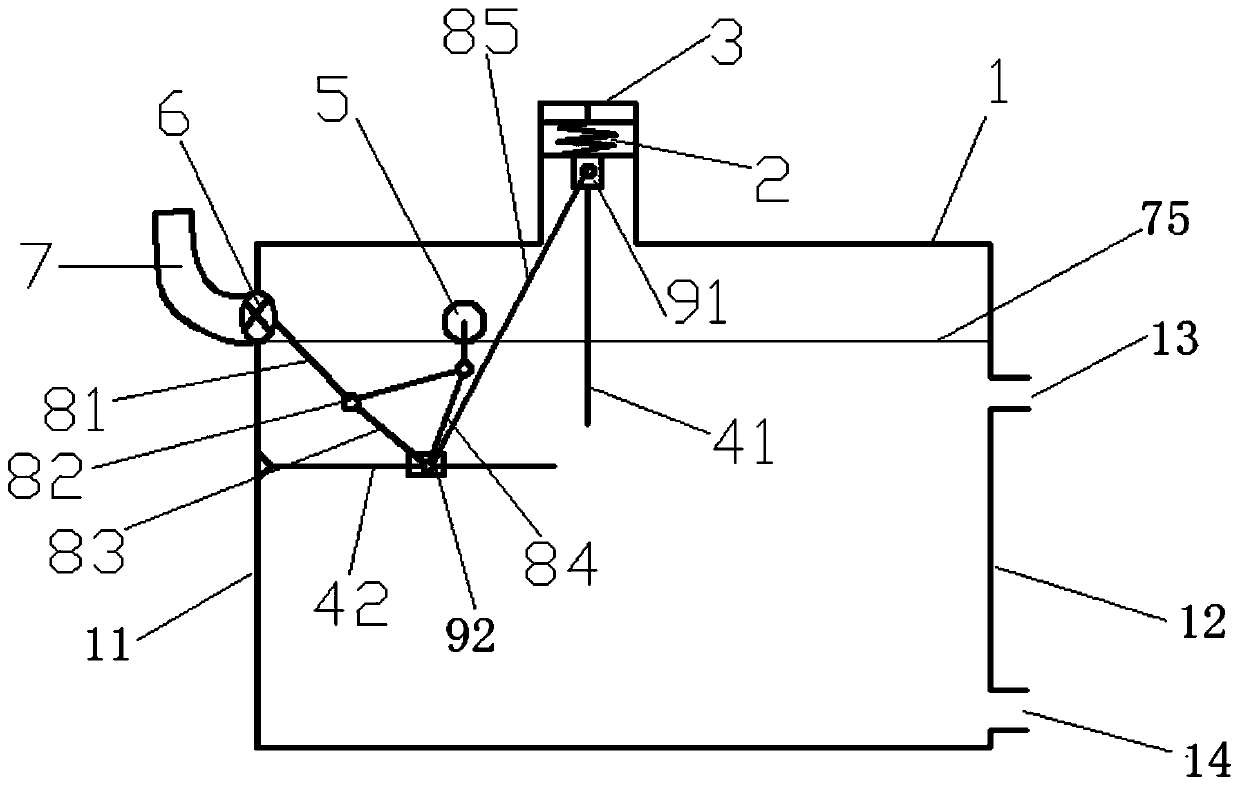
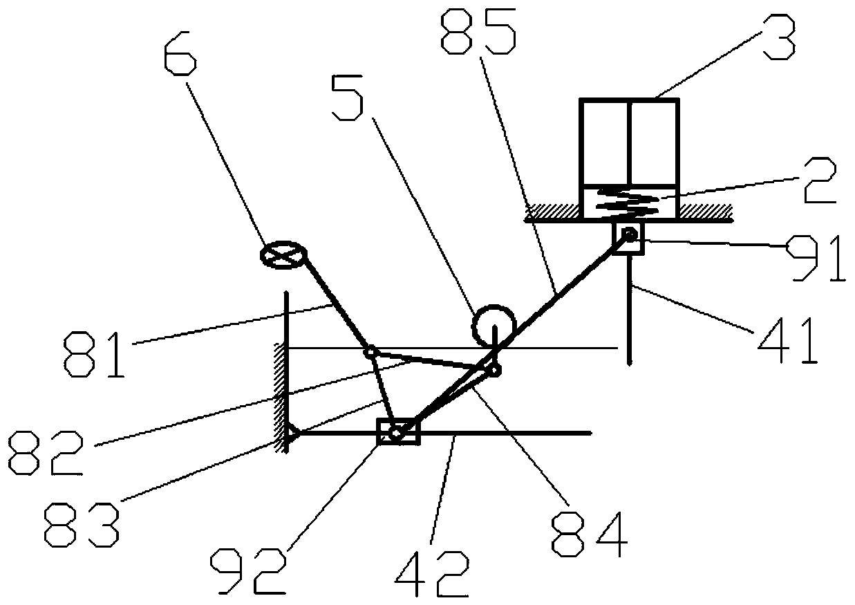
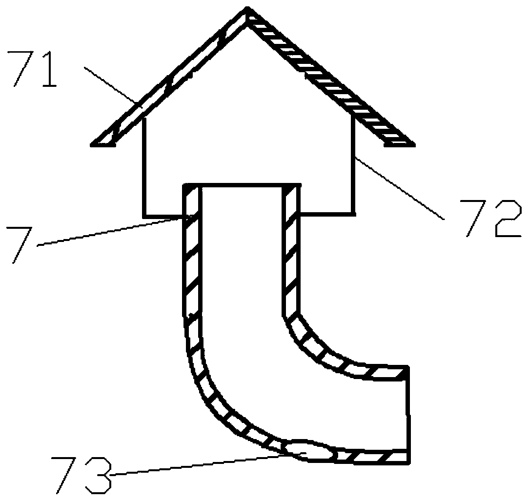
[0028] like figure 1 As shown, a solar water heater water tank exhaust device according to the present invention includes an insulated water tank 1, an exhaust tailpipe 7 is arranged on the outer side of the first side wall 11 of the insulated water tank 1, and the first side wall 11 is open on the top and communicates with the bottom port of the exhaust tail pipe 7. The opening of the first side wall 11 is provided with a seal 6 capable of sealing the first side wall 11. One end of the seal 6 is connected to the bottom port of the exhaust tail pipe 7. The opening of the first side wall 11 is hinged, and rubber is provided on the circumference of the sealing member 6, so that the sealing effect is better.

[0029] The second side wall 12 of the thermal insulation water t...


PUM


Abstract

The invention provides an air exhausting device for a water tank of a solar water heater. The air exhausting device for the water tank of the solar water heater comprises an insulating water tank, wherein an air exhausting tail tube is arranged on a side wall of the insulating water tank; a water inlet and a water outlet are formed in the other side wall of the insulating water tank; an air exhausting linkage device is arranged in the insulating water tank and comprises a floating ball, five connecting rods, a cross rod, a vertical rod, a first sliding block and a second sliding block; one endof the vertical rod is fixedly connected with an air storage tank at the top end of the water tank; three of the connecting rods form a triangle; a first vertex of the triangle formed by the connecting rods is connected with the floating ball; a second vertex of the triangle formed by the connecting rods is connected with the second sliding block; a third vertex of the triangle formed by the connecting rods is connected with a sealing piece through one connecting rod; the second sliding block and the first sliding block are separately connected with the cross rod and the vertical rod slidably; and the second sliding block is connected with the first sliding block through one connecting rod. By a principle of floating ball and connecting rod movement, air discharge in the water tank of thesolar water heater is controlled, and intensity of pressure in the water tank is balanced.

Description

technical field [0001] The invention relates to the field of solar water heaters, in particular to an exhaust device for a water tank of a solar water heater. Background technique [0002] At present, my country has become the world's largest solar water heater producer and solar water heater market, and this industry has also become a renewable energy industry that is at the world's leading level in terms of production capacity and utilization scale. [0003] The exhaust devices of solar water heaters are divided into drooping exhaust, overflow exhaust, and electric valve closing. The above three methods are single in technology, and they are only simple exhaust devices, without combining other performances to maximize the simplified water tank. However, the baking and exhausting device of the solar vacuum heat collecting tube has a higher cost and is not easy to maintain after the vacuum degree is reduced. In addition, there are some solar collector tube exhaust equipment...

Claims


Application Information

Patent Timeline
Patent Type & Authority Patents(China)
IPC IPC(8): F24S40/00
Inventor 高文宇潘秋红吕芙蓉于龙杰佘林月
Owner JIANGSU UNIV
Why Eureka
Try Eureka