
Method for detecting thermal design rationality of electronic product based on infrared thermal imaging technology

A technology of infrared thermal imaging and infrared thermal imager, which is applied in the direction of electronic circuit testing, radiation pyrometry, measuring devices, etc., can solve the problem of not being able to grasp the temperature convection and radiation of products, increasing the difficulty of testing personnel's work, and being unable to quickly and effectively measure and other issues, to eliminate the risk of test omissions, save test time, and cover comprehensive effects

Inactive Publication Date: 2018-07-20
SICHUAN JINWANGTONG ELECTRONICS SCI & TECH
View PDF6 Cites 3 Cited by
  • Summary
  • Abstract
  • Description
  • Claims
  • Application Information

AI Technical Summary

Problems solved by technology

Although the temperature test of single-point conduction can be realized, it cannot be quickly and effectively measured without dead ends, and the overall temperature convection and radiation of the product cannot be grasped. To achieve a comprehensive temperature distribution test of the product, it is necessary to test each point one by one, which greatly increases The work of testers is difficult, and the work efficiency is low. At the same time, it is easy to miss key points due to the experience and meticulousness of the testers.
Due to the limitation of the detection device, the device that is too small cannot be tested at all, and it becomes a blind area of ​​temperature rise management, leaving a fatal hidden danger to the product

Method used


Image

  • Method for detecting thermal design rationality of electronic product based on infrared thermal imaging technology
  • Method for detecting thermal design rationality of electronic product based on infrared thermal imaging technology
  • Method for detecting thermal design rationality of electronic product based on infrared thermal imaging technology

Examples


Embodiment Construction

[0028] The present invention will be further described below in conjunction with the accompanying drawings and specific embodiments.

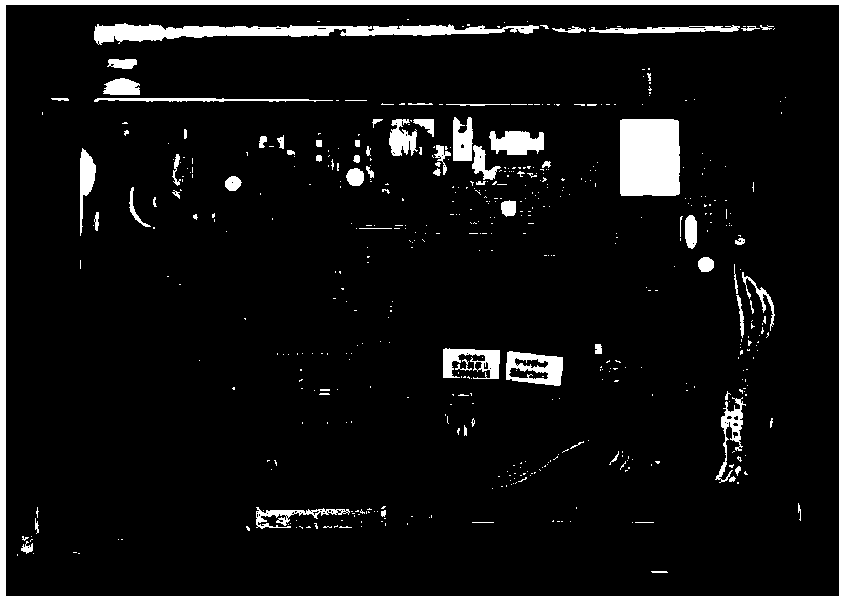
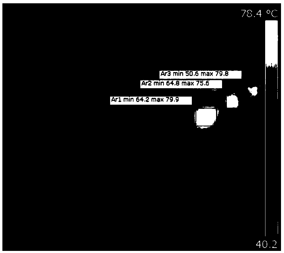
[0029] An embodiment of the present invention provides a method for detecting the rationality of thermal design of electronic products based on infrared thermal imaging technology, including: capturing infrared imaging data of the product to be tested by an infrared thermal imaging device, and transmitting the data to a computer , the computer analyzes and judges the measurement data through the set detection standards, so as to complete the detection of the rationality of the thermal design of electronic products.

[0030] The infrared thermal imager can be hand-held, portable, flexible, and fast-reading data. When the infrared thermal imager measures, its infrared lens is aimed at the test area of ​​the product to be tested, and there is no dead angle or blind area. Cover the tested area of ​​the product under test.

[0031] Data transmissio...


PUM


Abstract

The invention discloses a method for detecting the thermal design rationality of an electronic product based on an infrared thermal imaging technology, which comprises the steps that infrared imagingdata of a product to be detected is captured through an infrared thermal imaging instrument, the data is transmitted to a computer, and the computer analyzes and judges the measured data according toset detection standards so as to complete detection for the thermal design rationality of the electronic product. The infrared thermal imaging instrument is taken as a main body for detection, and only the handheld infrared thermal imaging instrument is required to be selected to perform detection on a normally operating or aging product; and the operation is flexible, the coverage is comprehensive, and the universality is high. Compared with the prior art, the operation difficulty can be reduced, the test time can be saved, and the risk of test omission is eliminated. The thermal design rationality serves as a necessary item for the hardware reliability in the research and development and sample design finalizing stages of the electronic product; thermal design defects are effectively measured and discovered before mass production of the electronic product, thereby performing rectification and remedy timely, and being capable of effectively reducing the failure rate and the quality cost of the electronic product after mass production.

Description

technical field [0001] The invention relates to a method for detecting electronic products, in particular to a method for detecting the rationality of thermal design of electronic products based on infrared thermal imaging technology. Background technique [0002] With the development of electronic technology, various electronic products are highly integrated, with dense circuits and tiny devices, more powerful functions, higher configurations, and faster operating speeds. However, if electronic products are used for a long time, the temperature rise of CPU, semiconductor tubes, high-power resistive capacitors, etc. will increase, and the performance and life will decrease sharply. At least it will cause the product to crash, and at the worst it will cause function failure and product burnout. As with all electronic devices, only within the appropriate temperature range can the device work properly and last. This is especially true for temperature-sensitive devices. For exa...

Claims


Application Information

Patent Timeline
Patent Type & Authority Applications(China)
IPC IPC(8): G01R31/28G01J5/00
CPCG01J5/00G01J2005/0077G01R31/2801
Inventor 李世凤
Owner SICHUAN JINWANGTONG ELECTRONICS SCI & TECH
Learn More