Self-adaptive motor

A motor, self-adaptive technology, applied in the direction of electric components, electrical components, electromechanical devices, etc., can solve the problems of limiting motor power, motor heating, etc., and achieve the effect of reliable connection or disconnection, system stability, and large stable power

Inactive Publication Date: 2018-07-20
朱虹斐
View PDF3 Cites 0 Cited by
  • Summary
  • Abstract
  • Description
  • Claims
  • Application Information

AI Technical Summary

Problems solved by technology

[0002] The motor has many application fields, and in some fields, the working conditions of the motor are more complicated, especially in the environment where the resistance torque fluctuates greatly, the working current of the motor fluctuates greatly, for example, when the resistance torque increases greatly, the working The current is greatly increased, and the motor heats up quickly; in view of this situation, the current selection requirements for the motor are that for those that may have a large working resistance, it is necessary to use a thicker copper wire excitation winding to prevent burning when a large current passes. Bad excitation winding; however, the thicker copper wire limits the power of the motor when it works smoothly; for this reason, the selection of motors under complex working conditions is a problem of taking one thing at the other

Method used


Image

  • Self-adaptive motor
  • Self-adaptive motor

Examples


Embodiment 1

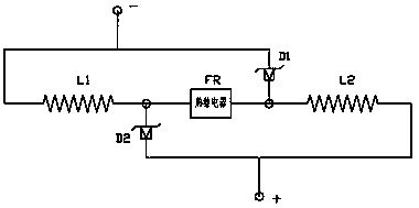
[0016] exist figure 1 In the first embodiment shown, each set of excitation windings includes two identical first windings L1 and second windings L2 connected in series; a thermal relay FR is connected in series between the first winding L1 and the second winding L2 ; A second node is formed between the first winding L1 and the thermal relay FR; a first node is formed between the second winding L2 and the thermal relay FR; the first winding L1 is not connected to the thermal relay One end of the FR connection is connected to the negative terminal of the power module (not shown), and the first node is also connected to the negative terminal of the power module after passing through the first Zener diode module D1; the second winding L2 The end not connected to the thermal relay FR is connected to the positive terminal of the power module, and the second node is also connected to the positive terminal of the power module after passing through the second Zener diode module D2.

...

Embodiment 2

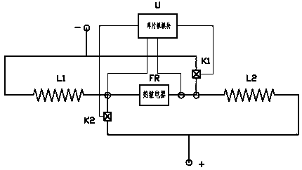
[0020] exist figure 2 In the second embodiment shown, each set of excitation windings includes two identical first windings L1 and second windings L2 connected in series; a thermal relay FR is connected in series between the first winding L1 and the second winding L2 ; A second node is formed between the first winding L1 and the thermal relay FR; a first node is formed between the second winding L2 and the thermal relay FR; the first winding L1 is not connected to the thermal relay FR One end of the connection is connected to the negative terminal of the power module (not shown), and the first node is also connected to the negative terminal of the power module after passing through the first electronic switch K1; the second winding L2 is not connected to the thermal One end of the relay FR connection is connected to the positive end of the power module, and the second node is also connected to the positive end of the power module after passing through the second electronic sw...


PUM


Abstract

The invention provides a self-adaptive motor, wherein each excitation winding of the motor comprises two identical windings connected in series, namely a first winding and a second winding. A thermalrelay is connected between the first winding and the second winding in series. A second node is formed between the first winding and the thermal relay. A first node is formed between the second winding and the thermal relay. One end, which is not connected with a thermal relay, of the first winding is connected to the negative pole end of the power supply module. The first node is also connected to the negative pole end of the power supply module through a first Zener diode module. One end, which is not connected with the thermal relay, of the second winding is connected to the positive pole end of the power supply module. The second node is also connected to the positive pole end of the power supply module through a second Zener diode module. When the self-adaptive motor works stably, theself-adaptive motor is equivalent to a fine-copper-wire excitation winding motor, wherein a large power can be provided by the motor. When the working current of the motor is large, the motor rapidlyheats up. That means, the motor is equivalent to a coarse-copper-wire excitation winding motor. Therefore, the excitation winding is prevented from being burnt out.

Description

technical field [0001] The invention relates to the field of electromechanical equipment, in particular to a DC motor. Background technique [0002] The motor has many application fields, and in some fields, the working conditions of the motor are more complicated, especially in the environment where the resistance torque fluctuates greatly, the working current of the motor fluctuates greatly, for example, when the resistance torque increases greatly, the working The current is greatly increased, and the motor heats up quickly; in view of this situation, the current selection requirements for the motor are that for those that may have a large working resistance, it is necessary to use a thicker copper wire excitation winding to prevent burning when a large current passes. Bad excitation winding; however, the thicker copper wire limits the power of the motor when it works smoothly; therefore, the selection of the motor under complex working conditions is a problem of taking c...

Claims


Application Information

Patent Timeline
Patent Type & Authority Applications(China)
IPC IPC(8): H02K3/00H02K11/25
CPCH02K3/00H02K11/25
Inventor 朱虹斐
Owner 朱虹斐
Why Eureka
Try Eureka