
A magnetic traction device

A magnetic traction and magnetic block technology, applied in the direction of fixator, external fixator, etc., can solve the problems of inconvenient adjustment, aggravating the physical and mental burden of patients, and lack of bone traction, so as to enhance the stimulation effect, improve the traction effect, and facilitate disassembly and installation. Effect

Inactive Publication Date: 2019-09-13
AFFILIATED YONGCHUAN HOSPITAL OF CHONGQING MEDICAL UNIV
View PDF9 Cites 0 Cited by
  • Summary
  • Abstract
  • Description
  • Claims
  • Application Information

AI Technical Summary

Problems solved by technology

Intramedullary nails are difficult to fix well in large bone defects, and do not have the ability of bone traction. It is often necessary to use bone transfer to fix each segment of bone from the outside. Osteotomy is done through trauma, slow pulling every day, and new long bone is used to repair the original bone defect. However, there are many needle holes and infection is easy to occur. At the same time, the bone is moved and fixed on the patient's body surface, which has a great impact on the daily life of the patient, and it is easy to increase the physical and mental burden of the patient. unfavorable for rehabilitation
The traditional tractable intramedullary nail is fixed by thread connection, and the bone needs to be forcibly pulled during adjustment, which makes the patient prone to discomfort and is inconvenient to adjust

Method used


Image

  • A magnetic traction device
  • A magnetic traction device
  • A magnetic traction device

Examples


Embodiment

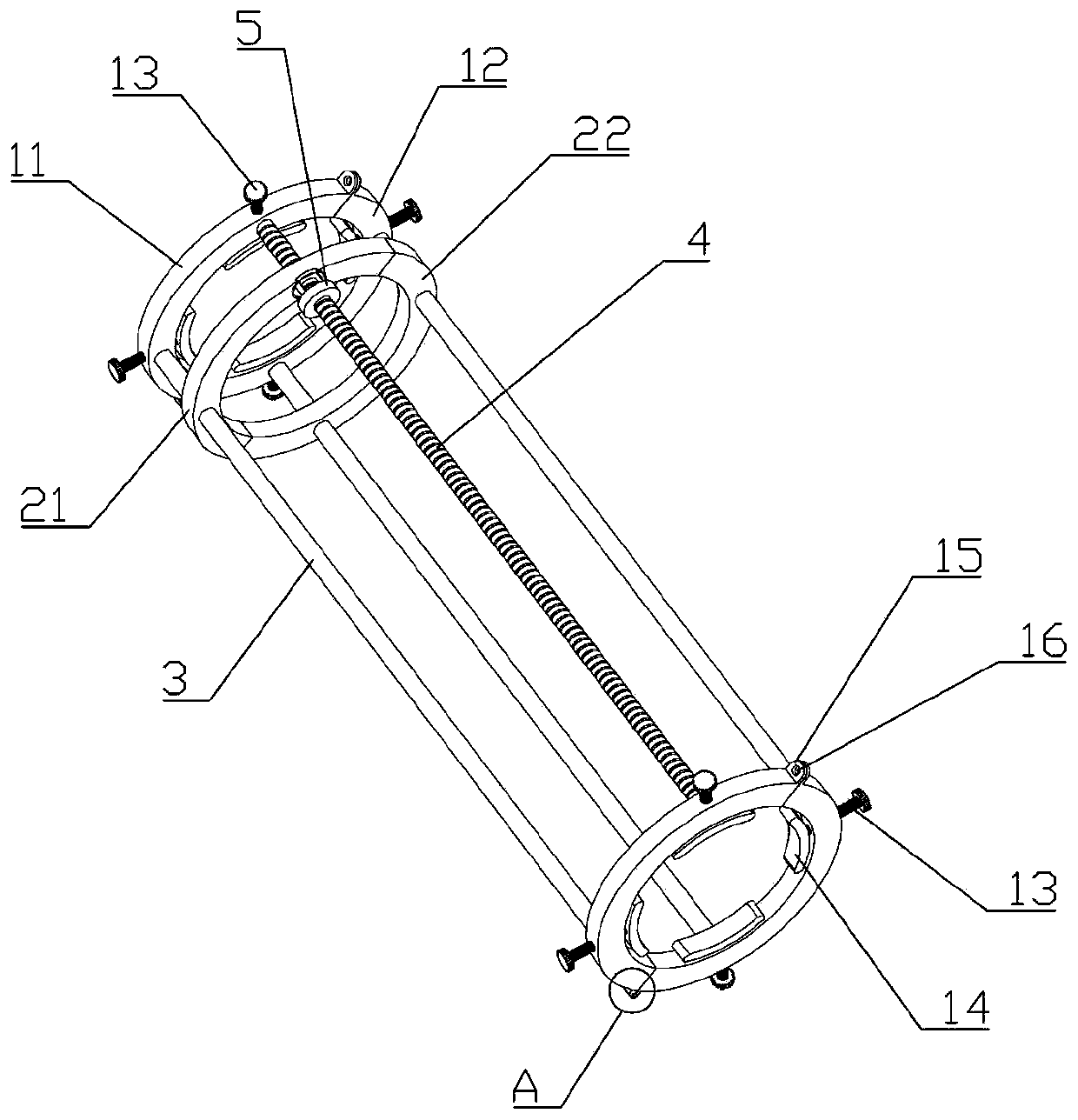
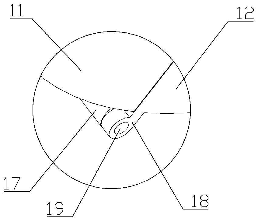
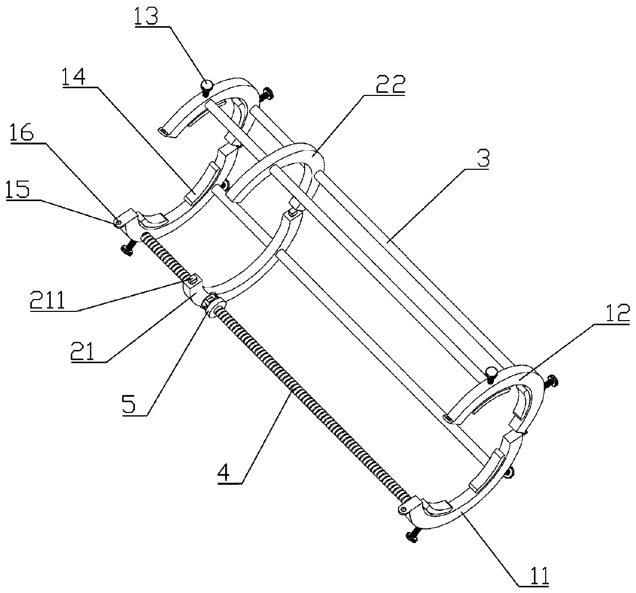
[0033] Such as Figure 1~6 As shown, a magnetic traction device includes an intramedullary rod arranged in the bone cavity and an intramedullary nail for fixing the bone and the intramedullary rod. Both ends of the magnetic traction device are provided with a first clasp 11 and a second clasp Ring 12, one end of the first snap ring 11 and the second snap ring 12 are hinged, and the other end is provided with a fixed ear plate 15, and a connecting hole 16 is provided on the fixed ear plate 15, and the first snap ring 11 and the second snap ring 12 The outer wall is radially provided with threaded through holes, and the threaded through holes are provided with an adjusting screw 13, and the adjusting screw 13 has a positioning card 14 on the ball hinge in the ring where the first snap ring 11 is located, and the first snap ring at both ends of the magnetic traction device 11 are connected with cylindrical guide rods 3 and threaded guide rods 4 with equal outer diameters, the fir...


PUM


Abstract

The invention belongs to the technical field of medical equipment, and mainly relates to a magnetic force traction device. The magnetic force traction device comprises an intramedullary rod which is arranged in the bone cavity and an intramedullary nail which fixes the bone and the intramedullary rod, first clamping rings and second clamping rings are arranged at both ends of the magnetic force traction device, the first clamping rings are hinged to one ends of the second clamping rings, fixed lug plates are arranged at the other ends of all the first clamping rings and the second clamping rings, connecting holes are formed in all the fixed lug plates, threaded through holes are radially formed in the outer side walls of all the first clamping rings and the second clamping rings, and are internally provided with adjusting screws, locating clamps are spherically hinged to the portions, in circular rings where the first clamping rings are located, of the adjusting screws, cylindrical guide rods and threaded guide rods with the equal outer diameter are connected to the first clamping rings at the two ends of the magnetic force traction device, and second electromagnets slidably sleevethe portion, on the cylindrical guide rods, between the second clamping rings. By means of the magnetic force traction device, the infection problem of puncturing holes is solved while the burden ofa patient is relieved, traction is convenient, and discomfort is not easily caused.

Description

technical field [0001] The invention belongs to the technical field of medical equipment, and in particular relates to a magnetic traction device. Background technique [0002] The intramedullary nail is an internal fixation device in the bone marrow cavity of the human body, and is a commonly used medical device for the treatment of fractures. The intramedullary nail is located in the bone marrow cavity and connects the fractured long tubular bone through the intramedullary nail body and the locking nail. It has the functions of aligning the fracture fragments, fixing them, and supporting a certain gravity, so as to facilitate the growth of callus and fracture healing. . Intramedullary nails are difficult to fix well in large bone defects, and do not have the ability of bone traction. It is often necessary to use bone transfer to fix each segment of bone from the outside. Osteotomy is done through trauma, slow pulling every day, and new long bone is used to repair the ori...

Claims


Application Information

Patent Timeline
Patent Type & Authority Patents(China)
IPC IPC(8): A61B17/62A61B17/64
Inventor 刘伟
Owner AFFILIATED YONGCHUAN HOSPITAL OF CHONGQING MEDICAL UNIV
Learn More