Network chain oil separation machine

An oil separator and mesh chain technology, applied in filtration separation, liquid separation, separation methods, etc., can solve the problems of surface lipophilicity requiring regular replacement, occupying a large space, and increasing oil-water separation equipment.

Pending Publication Date: 2018-07-24
烟台开发区博森科技发展有限公司
View PDF0 Cites 1 Cited by
  • Summary
  • Abstract
  • Description
  • Claims
  • Application Information

AI Technical Summary

Problems solved by technology

The sticky oil belt of such an oil separator increases with the use time, and the lipophilicity of the surface is worn and needs to be replaced regularly, which increases the user's use and maintenance costs; the two-stage oil receiving box causes the oil separator to occupy a large installation space as a whole
[0003] The existing oil-water separation device uses a stainless steel mesh belt to stick to the slick oil, and then scrapes the slick oil stuck on the mesh belt into the oil guide groove through the scraper, and then guides it into the oil slick collection area through the oil guide groove. It solves the problem that the sticky oil belt will be damaged by long-term use of lipophilicity, but the stainless steel mesh belt has a small weight. In order to ensure that the stainless steel mesh belt rotates with the drive shaft, the lower end of the stainless steel mesh belt must fall into the roller, and the scraper scraped from the mesh belt is not only It is only the oil slick adhering to the mesh belt, and there is a large amount of emulsion. Therefore, firstly, the oil-water mixture collected in the oil slick collection area must be statically separated by the difference in specific gravity of oil and water. Static separation seriously affects the oil-water separation efficiency. Secondly, the existing The floating oil collection area is set on the side of the oil-water separation device, which occupies a large space and increases the footprint of the oil-water separation device. Finally, only one adhesion of one oil-water separation device cannot meet the requirements of oil-water separation
Therefore, it is necessary to design two or more oil-water separation devices to achieve multi-stage separation. The oil-water separation device in the latter stage will separate the oil from the oil-water separation device in the previous stage to separate the oil from water in order to achieve the purpose of oil-water separation. With the increase of separation equipment, it is necessary to equip the corresponding floating oil collection area, which not only increases the cost of oil-water separation, but also requires more installation space and occupies a large area.

Method used


Image

  • Network chain oil separation machine
  • Network chain oil separation machine
  • Network chain oil separation machine

Examples


Embodiment Construction

[0040] The principles and features of the present invention are described below in conjunction with examples, which are only used to explain the present invention and are not intended to limit the scope of the present invention.

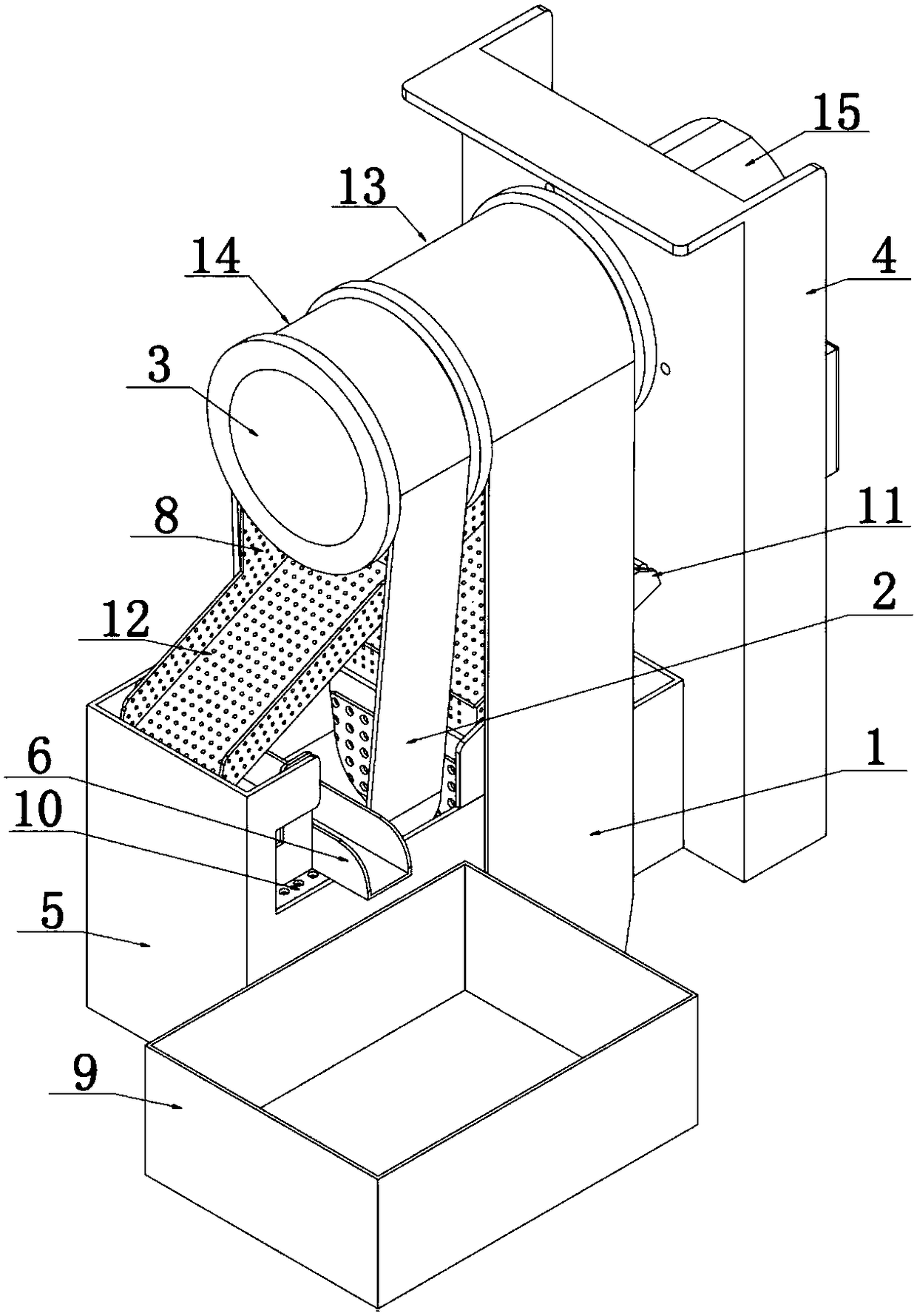
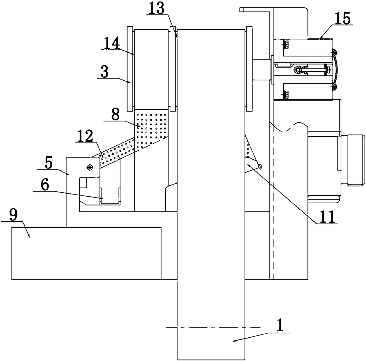
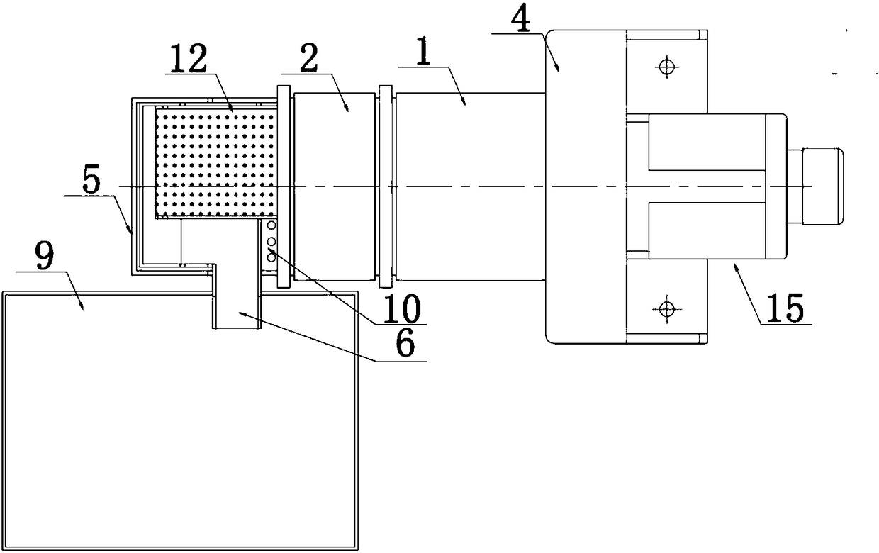
[0041] Such as Figure 1-Figure 8 As shown, a network chain oil separator includes a frame 4, a network chain transmission shaft 3 arranged on the frame, a primary separation mechanism, a secondary separation mechanism, an oil return layered collection box 5, and an oil return tank 6. The transmission shaft of the net chain rotates under the action of the power mechanism;

[0042] The primary separation mechanism includes a primary mesh chain 1 and a primary oil scraper 7, the secondary separation mechanism includes a secondary mesh chain 2 and a secondary oil scraper 8, the primary mesh chain and the secondary oil scraper 8 The stage net chain is a closed loop belt structure, the upper ends of the first class net chain and the second class net chai...


PUM


Abstract

The invention discloses a network chain oil separation machine. The network chain oil separation machine comprises a rack, and a network chain transmission shaft, a first-grade separation mechanism, asecond-grade separation mechanism, an oil returning and layered collection box and an oil returning groove which are arranged on the rack, wherein the network chain transmission shaft rotates under the action of a power mechanism; the first-grade separation mechanism comprises a first-grade network chain and a first-grade oil liquid scraping plate; the second-grade separation mechanism comprisesa second-grade network chain and a second-grade oil liquid scraping plate; the upper ends of the first-grade network chain and the second-grade network chain are wound on the network chain transmission shaft respectively; the lower end of the first-grade network chain stretches into an emulsified liquid tank; the lower end of the second-grade network chain stretches into the oil returning and layered collection box; the oil returning groove is formed in the lower side of the second-grade oil liquid scraping plate; an outlet of the oil returning groove is communicated to an oil receiving box. The network chain oil separation machine disclosed by the invention is simple in structure and small in occupied space; two-grade separation can be realized through the device; the second-grade networkchain can be used for separating separated oil liquid again; the water content of the separated oil liquid can be ignored; no consumable items need to be replaced, and overhauling and maintaining time is saved; the utilization cost of a user is reduced.

Description

technical field [0001] The invention relates to a network chain oil separator, which belongs to the technical field of oil-water separation. Background technique [0002] At present, the belt-type oil-water separation device used in machine tools uses the sticky oil belt to absorb and collect the slick oil floating on the surface of the emulsion. When the oil is on the surface, there is a large amount of emulsion at the bottom of the oil collected in the oil receiving box, so it is necessary to make a two-stage oil receiving box, the first stage separates the residual water in the emulsion, and the second stage is used as a floating oil collection box . The sticky oil belt of such an oil separator increases with the use time, and the lipophilicity of the surface is worn and needs to be replaced regularly, which increases the user's use and maintenance costs; the two-stage oil receiving box causes the oil separator to occupy a large installation space as a whole. [0003] T...

Claims


Application Information

Patent Timeline
Patent Type & Authority Applications(China)
IPC IPC(8): B01D17/032B01D29/01B01D36/00
CPCB01D17/0214B01D29/01B01D36/003
Inventor 周博张芳芳纪艳青徐俊彦蒋兆垣高伟刘开艇韩喜峰
Owner 烟台开发区博森科技发展有限公司
Why Eureka
Try Eureka