External oil separator of horizontal screw machine with oil reservoir

A technology of oil separator and oil storage, which is applied in the direction of separation method, dispersed particle separation, dispersed particle filtration, etc. It can solve the problems of prolonging cleaning time and use time, difficult cleaning, inconvenient disassembly and assembly, etc., and achieves prolonging cleaning time and Use time, solve the effect of cleaning difficulties

Inactive Publication Date: 2018-07-24
宁波中倚机电科技发展有限公司
View PDF0 Cites 0 Cited by
  • Summary
  • Abstract
  • Description
  • Claims
  • Application Information

AI Technical Summary

Problems solved by technology

[0003] The purpose of the present invention is to overcome the deficiencies of the above-mentioned prior art, and provide a horizontal screw machine external oil separator with an oil reservoir, including an intake baffle assembly, a filter assembly, a cylinder, an oil reservoir, and the cylinder and The left head and the right head are connected into a sealed whole, the air intake pipe is connected to the inner cavity from the upper left end of the cylinder body, the air outlet pipe is connected to the outside from the right end of the inner cavity of the cylinder body, and the air intake baffle assembly is arranged on the left side of the end of the inner air intake pipe. The right end of the air intake baffle assembly is provided with two filter screen assemblies side by side, the right end of the filter screen assembly on the right is provided with an air outlet baffle, the lower end of the right side of the cylinder body is externally connected to an oil reservoir, and the cylinder wall of the oil reservoir is provided with a sight glass. Liquid mirror 2, the oil return joint of the oil storage device, the oil return pipe, and the interface of the heating pipe. Difficult cleaning, inconvenient disassembly and assembly, etc., the compressed air passes through three layers to absorb oil, and can flow into the oil storage at the bottom of the cylinder, which greatly prolongs the cleaning time and use time

Method used


Image

  • External oil separator of horizontal screw machine with oil reservoir
  • External oil separator of horizontal screw machine with oil reservoir
  • External oil separator of horizontal screw machine with oil reservoir

Examples


Embodiment Construction

[0017] The technical solutions of the present invention will be further specifically described below through the embodiments and in conjunction with the accompanying drawings.

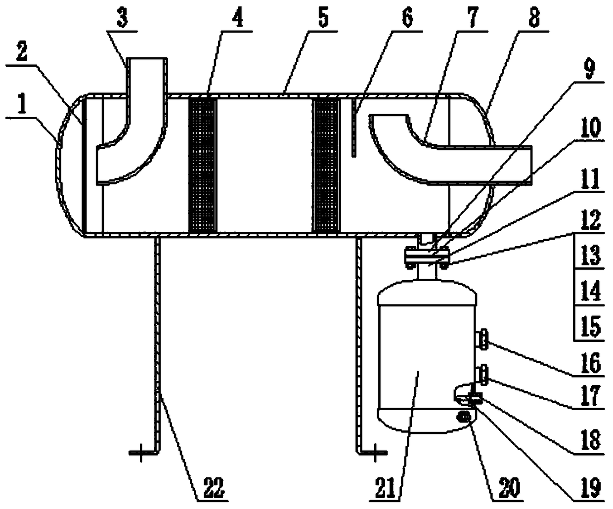
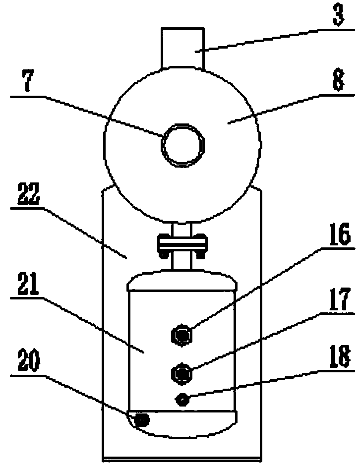
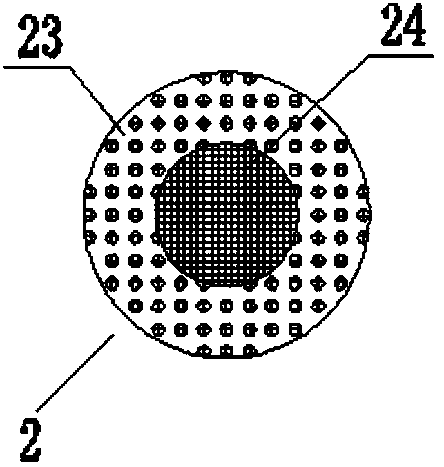
[0018] like Figure 1 ~ Figure 4 As shown, the external oil separator of a horizontal screw machine with an oil reservoir includes an intake baffle assembly 2, a filter screen assembly 4, a cylinder body 5, and an oil reservoir 21. The cylinder body 5 and the left head 1 , the right head 8 is connected into a sealed whole, the air inlet pipe 3 is connected to the inner cavity from the upper left end of the cylinder body 5, the air outlet pipe 7 is in contact with the outside from the right end of the inner cavity of the cylinder body 5, and the end of the inner air inlet pipe 3 is left The intake baffle assembly 2 is arranged on the side, and the filter screen A24 of the baffle assembly 2 is used to absorb the oil in the high-pressure gas entering. The second and third times of oil adsorption greatly ...


PUM


Abstract

The invention discloses an external oil separator of a horizontal screw machine with an oil reservoir. The external oil separator comprises an air inlet baffle assembly, filtering net assemblies, a cylinder and an oil reservoir, wherein the cylinder is connected with a left seal head and a right seal head to form a sealed whole; an air inlet tube is connected to an inner cavity from the left upperend of the cylinder, and an air outlet tube is contacted with outside from a right-end position of the inner cavity of the cylinder; the air inlet baffle assembly is arranged on the left side of thetail end of the inner air inlet tube; two filtering net assemblies are arranged at the right end of the air inlet baffle assembly in parallel; an air outlet baffle is arranged at the right end of thefiltering net assembly on the right side; the lower end of the right side of the cylinder is externally connected with the oil reservoir; a sight glass I, a sight glass II, an oil reservoir oil returnconnector, an oil return tube and a heating tube joint are arranged on cylindrical walls of the an oil reservoir. The original built-in oil separator is modified as an external manner, is connected with the cylinder into a whole and is provided with the oil reservoir, and the problems that the original built-in structure is difficult to clean and inconvenient to detach and the like are solved. Compressed air is subjected to three-layer oil dirt adsorption and can flow into the oil reservoir at the bottom of the cylinder, and the cleaning time and using time can be greatly prolonged.

Description

technical field [0001] The invention relates to the technical field of process equipment, in particular to an external oil separator for a horizontal screw machine with an oil reservoir. Background technique [0002] like Figure 5 As shown: the built-in oil separator of the horizontal screw air compressor is installed in the cylinder body 1001 of the gas storage, and an inner sleeve 1002 with uniformly distributed air inlet holes on the periphery and bottom is arranged in the cylinder body 1001, and the inner sleeve 1002 Several layers of stainless steel rhombic wire mesh 1004 are laid on the bottom of the inner cavity, and the upper cover of the stainless steel rhombic wire mesh 1004 is a wire mesh baffle 1003. After the high-pressure gas enters the cylinder one 1001 from the air inlet 1005, it passes through the inner sleeve 1002 and lays the bottom of the inner cavity. Several layers of stainless steel diamond-shaped wire mesh 1004 absorb the oil in the high-pressure air...

Claims


Application Information

Patent Timeline
Patent Type & Authority Applications(China)
IPC IPC(8): B01D46/00B01D46/12B01D46/42
CPCB01D46/0043B01D46/0049B01D46/12B01D46/4263B01D46/64
Inventor 孔珍珍
Owner 宁波中倚机电科技发展有限公司
Why Eureka
Try Eureka