Anti-suspension device for high-purity graphite carbon material bin and using method
A technology of high-purity graphite and carbon materials, applied in packaging, loading/unloading, transportation and packaging, etc., can solve problems such as adhesion, reduced material output, deformation, etc., to achieve the effect of wasting manpower and increasing cleaning time
- Summary
- Abstract
- Description
- Claims
- Application Information
AI Technical Summary
Problems solved by technology
Method used
Image
Examples
specific Embodiment approach 1
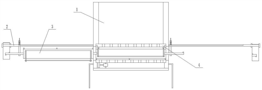
[0021] Specific implementation mode one: as Figure 1-7 As shown, this embodiment describes a high-purity graphite carbon material bin anti-suspension device, including a bin 1, two control devices 2, two conveying devices 3 and a discharge device 4; the inside of the bin 1 is set There is a discharge device 4, and two control devices 2 are arranged symmetrically on both sides of the silo 1;
specific Embodiment approach 2
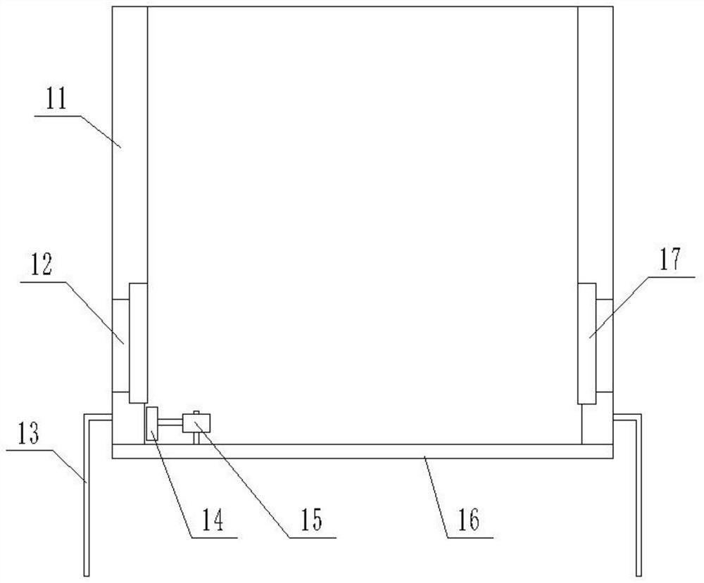
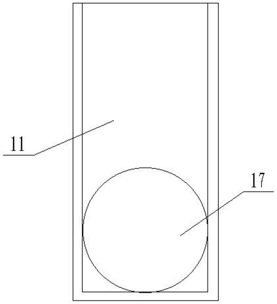
[0022] Specific implementation mode two: as figure 2 , 3 As shown, this embodiment is a further description of specific embodiment one. The silo 1 includes a silo main body 11, a bracket 13, a gear 14, a motor 15 and a bottom plate 16; the upper and lower parts of the silo main body 11 Both ends are hollowed out, and a round hole I12 is provided on the outside of the side wall of the silo main body 11, and a round hole II17 is provided on the inside of the side wall of the silo main body 11; the bottom plate 16 is fixedly connected to the bottom of the silo main body 11 by bolts , the motor 15 is fixedly connected to the upper end of the bottom plate 16 through a bracket, and the output shaft of the motor 15 is fixedly connected with a gear 14;
specific Embodiment approach 3
[0023] Specific implementation mode three: as Figure 4 As shown, this embodiment is a further description of Embodiment 1. Each of the control devices 2 includes two baffles 21, a fixed rod 22, a limit block 23, a limit rod 29, a spring 211, and a slider. 212 and a vertical bar 213; the side of the limiting block 23 is provided with a through hole 26 that runs through the limiting block transversely, and one side of the limiting block 23 is provided with a circular hole III25, and the outer side of the circular hole III25 is also provided with a spiral groove I24 The fixed rod 22 is slidingly fitted with the through hole 26, and the upper end of the fixed rod 22 is fixedly connected with two baffles 21, and the limit block 23 is located between the two baffles 21; the one end is fixedly connected to the through hole 26 On the top wall, the other end of is fixedly connected to the upper end of the fixed rod 22; the upper end of the fixed rod 22 is also provided with a chute 28...
PUM
 Abstract
Description
Claims
Application Information
 - R&D
- Intellectual Property
- Life Sciences
- Materials
- Tech Scout
- Unparalleled Data Quality
- Higher Quality Content
- 60% Fewer Hallucinations
Browse by: Latest US Patents, China's latest patents, Technical Efficacy Thesaurus, Application Domain, Technology Topic, Popular Technical Reports.
© 2025 PatSnap. All rights reserved.Legal|Privacy policy|Modern Slavery Act Transparency Statement|Sitemap|About US| Contact US: help@patsnap.com


