Compressor valve assembler

A technology of compressors and assemblers, which is applied in the direction of hand-held tools and manufacturing tools, can solve the problems of complex and large working platform structures, difficult replacement and maintenance, etc., and achieve the effects of shortening maintenance time, improving work efficiency and reducing operation risks

Inactive Publication Date: 2018-07-24
SHANDONG BAOTA NEW ENERGY CO LTD
View PDF0 Cites 0 Cited by
  • Summary
  • Abstract
  • Description
  • Claims
  • Application Information

AI Technical Summary

Problems solved by technology

[0004] The purpose of the present invention is to provide a compressor valve assembler aiming at the technical defects of the prior art, so as to solve the problem that the structure of the working platform used for compressor valve assembly in the prior art is relatively complex and bulky, so it is difficult to install the compressor on the spot Perform technical issues with replacement repairs

Method used


Image

  • Compressor valve assembler
  • Compressor valve assembler
  • Compressor valve assembler

Examples


Embodiment 1

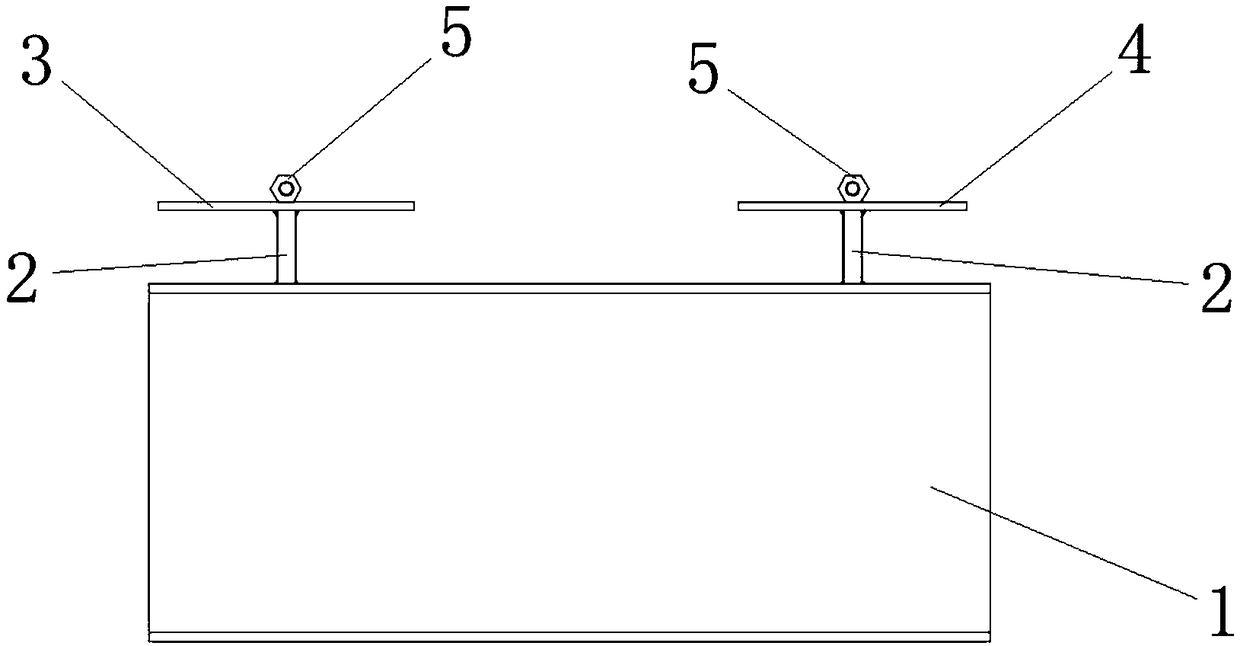
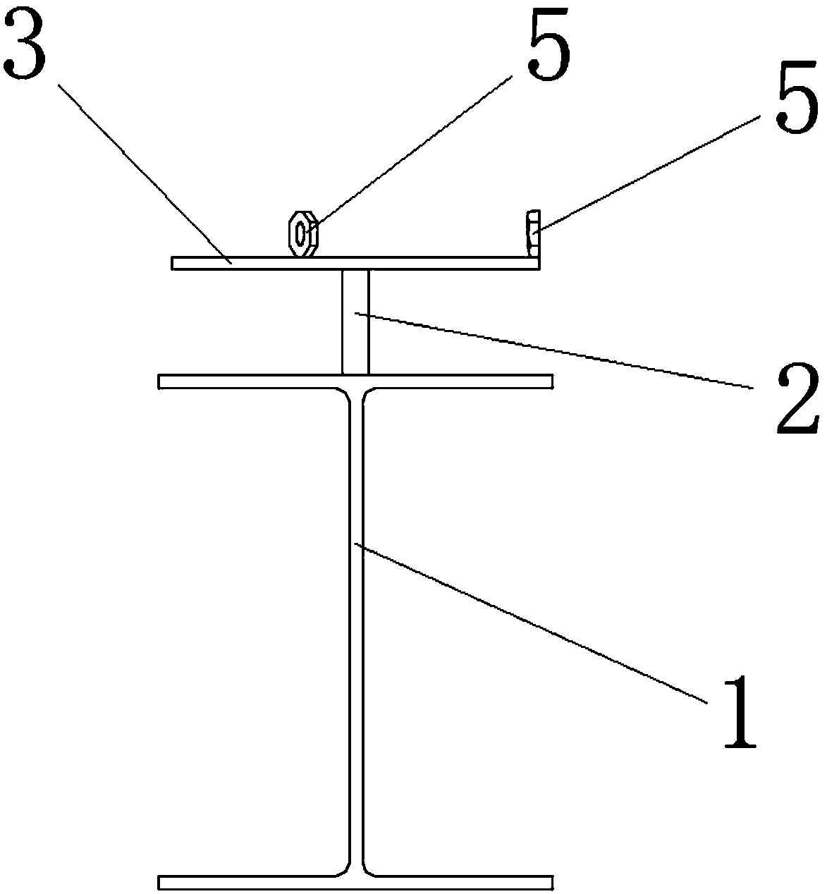
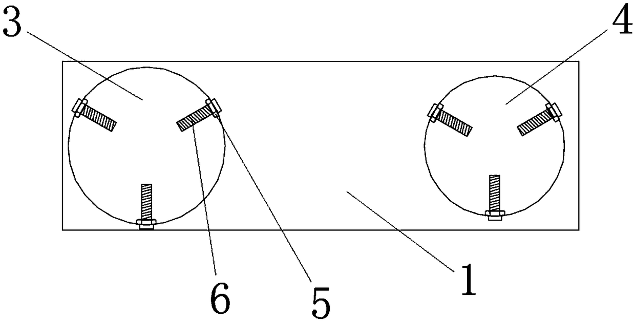
[0023] Compressor valve assembler, such as Figure 1~3 As shown, it includes H steel 1, steel pipe 2, first circular steel plate 3, second circular steel plate 4, nut 5, and bolt 6, wherein the two ends of the upper surface of H steel 1 are respectively welded with a steel pipe 2 and two steel pipes 2 All in a vertical state, the top of one of the steel pipes 2 is welded with a first circular steel plate 3, the top of the other steel pipe 2 is welded with a second circular steel plate 4, the first circular steel plate 3 and the second circular steel plate 4 are both It is horizontal; the upper surface edge of the first circular steel plate 3 is welded with three nuts 5, and the three nuts 5 are evenly distributed along the upper surface edge of the first circular steel plate 3, and the axes of the three nuts 5 intersect at One point, this point is located on the axis of the first circular steel plate 3; The upper surface edge of the second circular steel plate 4 is welded with...

Embodiment 2

[0026] Compressor valve assembler, such as Figure 1~3 As shown, it includes H steel 1, steel pipe 2, first circular steel plate 3, second circular steel plate 4, nut 5, and bolt 6, wherein the two ends of the upper surface of H steel 1 are respectively welded with a steel pipe 2 and two steel pipes 2 All in a vertical state, the top of one of the steel pipes 2 is welded with a first circular steel plate 3, the top of the other steel pipe 2 is welded with a second circular steel plate 4, the first circular steel plate 3 and the second circular steel plate 4 are both It is horizontal; the upper surface edge of the first circular steel plate 3 is welded with three nuts 5, and the three nuts 5 are evenly distributed along the upper surface edge of the first circular steel plate 3, and the axes of the three nuts 5 intersect at One point, this point is located on the axis of the first circular steel plate 3; The edges of the upper surface are evenly distributed, and the axes of th...


PUM


Abstract

The invention provides a compressor valve assembler and belongs to the technical field of machine tools. According to the technical scheme, H steel is used as a basic platform of the device, steel pipes support circular steel plates through welding, the two circular steel plates with different diameters are used as a platform for disassembling a circulating hydrogen compressor air valve and a platform for disassembling a make-up hydrogen compressor air valve, nuts are welded onto the circular steel plates, bolts are in screw joint onto the nuts, the expansion and contraction quantity of each bolt is adjusted through a spanner when in use, and one end of a screw rod contacts the side surface of the corresponding air valve, so that the air valves are clamped and fixed. Through the assembler,and by cooperating with the relevant double offset ring spanner or a ring wrench, the air valves can be disassembled and assembled on overhaul sites. The compressor valve assembler provided by the invention can be used as a special tool for disassembling and installing the compressor valves, so that the working efficiency of reciprocating compressor unit maintenance is improved, the operation risk of reciprocating compressor unit maintenance is reduced, the unit maintenance time is shortened, and the equipment operating period is prolonged.

Description

technical field [0001] The invention relates to the technical field of mechanical tools, in particular to a compressor air valve assembler. Background technique [0002] Compressors play a very important role in the petrochemical industry. During the operation of the reciprocating compressor, the crankshaft drives the piston to perform high-speed reciprocating motion, and the reciprocating motion of the piston drives the intake and exhaust valves to switch and close continuously. After a long period of operation, the valve is prone to wear and affect the efficiency of the compressor. When inspecting and replacing the valve slices, it is necessary to open the air valve to check the valve slices and valve seats and replace and clean up foreign objects. If such work is performed on each air valve, it is necessary to go to the maintenance workshop with a working platform and special tools. This will result in long maintenance time, delay in production and waste of manpower. ...

Claims


Application Information

Patent Timeline
Patent Type & Authority Applications(China)
IPC IPC(8): B25B27/24
CPCB25B27/24
Inventor 肖凯文王宏涛王继龙张震贾磊
Owner SHANDONG BAOTA NEW ENERGY CO LTD
Why Eureka
Try Eureka