
Multifunctional road roller

A road roller and multi-functional technology, which is applied in the field of multi-functional road rollers, can solve the problems of increasing construction costs, increasing operating costs, and the single function of road rollers, and achieves the effects of speeding up construction, saving construction costs, and improving work efficiency

Inactive Publication Date: 2018-07-24
吴晓丽
View PDF8 Cites 5 Cited by
  • Summary
  • Abstract
  • Description
  • Claims
  • Application Information

AI Technical Summary

Problems solved by technology

[0002] Road rollers belong to the category of road equipment in construction machinery. They are widely used in the filling and compaction operations of large-scale engineering projects such as high-grade highways, railways, airport runways, dams, and stadiums. They can roll sandy, semi-cohesive and cohesive soils, Asphalt stabilized soil and asphalt concrete pavement layer, when rolling the asphalt concrete pavement, due to the adhesion of asphalt, there will inevitably be asphalt on the steel wheel, which will affect the operation. At present, the road roller generally only has a single function of rolling the road. Some problems are often encountered during the process, and other equipment is needed at this time, which will not only increase the cost of the operation, but also cause delays in the project. In addition, the steel wheels will damage the road surface when driving on normal roads. It is allowed to drive directly on the road, especially for short-distance transfers, which is extremely inconvenient, and when using ordinary trucks for transfer, a crane is required to lift and increase the construction cost. Finally, it is inevitable that the dust on the road will be blown everywhere during the operation, causing pollution to the environment

Method used


Image

  • Multifunctional road roller
  • Multifunctional road roller
  • Multifunctional road roller

Examples


Embodiment Construction

[0020] The following will clearly and completely describe the technical solutions in the embodiments of the present invention with reference to the accompanying drawings in the embodiments of the present invention. Obviously, the described embodiments are only some, not all, embodiments of the present invention. Based on the embodiments of the present invention, all other embodiments obtained by persons of ordinary skill in the art without making creative efforts belong to the protection scope of the present invention.

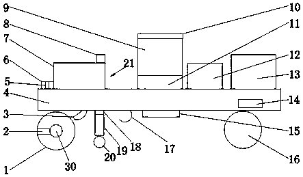
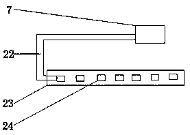
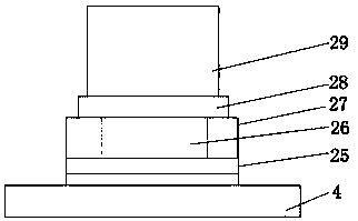
[0021] see Figure 1-4 , the present invention provides a technical solution: a multifunctional road roller, including a frame 4, a steel wheel 1 is provided on the left side of the bottom of the frame 4 and a driving wheel 16 is provided on the right side, and a rotating seat 11 is provided in the middle of the upper end of the frame 4 , the swivel seat 11 is provided with a cab 9, and the top of the cab 9 is provided with a solar receiver 10. The newly desig...


PUM


Abstract

The invention discloses a multifunctional road roller. The multifunctional road roller mainly comprises a rack, wherein a steel wheel is arranged on the left side of the bottom of the rack and travelling wheels are arranged on the right side of the rack; a rotating seat is arranged at the middle of the upper end of the rack; a driving cab is arranged on the rotating seat; a solar receiver is arranged at the top end of the driving cab; a power device is arranged on one side of the upper end of the rack; a lifting device is arranged on one side of the power device; hydraulic control type supporting legs are arranged on two sides of the rack; two ends of the outer side of a central shaft of the steel wheel are connected with supporting arms in parallel; the top ends of the supporting arms areconnected with a bumper; a dust remover is also arranged at the bottom middle of the rack. The multifunctional road roller disclosed by the invention adopts a simple structure and reasonable design;a single road roller is enabled to have multiple functions; the working face of the road roller is expanded so as to meet the demands of multiple working environments.

Description

technical field [0001] The invention relates to the technical field of construction machinery equipment, in particular to a multifunctional road roller. Background technique [0002] Road rollers belong to the category of road equipment in construction machinery. They are widely used in the filling and compaction operations of large-scale engineering projects such as high-grade highways, railways, airport runways, dams, and stadiums. They can roll sandy, semi-cohesive and cohesive soils, Asphalt stabilized soil and asphalt concrete pavement layer, when rolling the asphalt concrete pavement, due to the adhesion of asphalt, there will inevitably be asphalt on the steel wheel, which will affect the operation. At present, the road roller generally only has a single function of rolling the road. Some problems are often encountered during the process, and other equipment is needed at this time, which will not only increase the cost of the operation, but also cause delays in the pr...

Claims


Application Information

Patent Timeline
IPC IPC(8): E01C19/26E01H3/02E01H1/08
Inventor 吴晓丽
Owner 吴晓丽
Learn More