Dredging device and crane with dredging device

A dredging device and sliding column technology, which is applied to mechanically driven excavators/dredgers, earth movers/shovels, construction, etc., can solve the problems of high labor intensity for workers, low efficiency of sludge treatment, dredging and grabbing Low efficiency and other problems, to achieve a wide range of dredging, easy to manufacture and install on a large scale, to ensure the effect of stability and safety

Active Publication Date: 2018-07-24
湖南铭狮机械有限公司
View PDF6 Cites 1 Cited by
  • Summary
  • Abstract
  • Description
  • Claims
  • Application Information

AI Technical Summary

Problems solved by technology

[0002] At present, the dredging work of urban living or industrial inspection wells is generally manual dredging and manual underground operations. The efficiency of sludge treatment is low, the labor intensity of workers is high, and the working environment is harsh; the existing dredging mechanism cannot flexibly dredge inside the inspection well. , can only work in a straight line perpendicular to the wellhead, so that the dredging range is small and the dredging is not complete; and during the dredging process, the weight of the grab bucket itself enters the dredging sludge, and human control will inevitably lead to low dredging grabbing rate, When encountering branches or hard objects, it will cause problems such as incomplete dredging

Method used


Image

  • Dredging device and crane with dredging device
  • Dredging device and crane with dredging device
  • Dredging device and crane with dredging device

Examples


Embodiment Construction

[0023] Embodiments of the technical solutions of the present invention will be described in detail below in conjunction with the accompanying drawings. The following examples are only used to illustrate the technical solutions of the present invention more clearly, and therefore are only examples, rather than limiting the protection scope of the present invention.

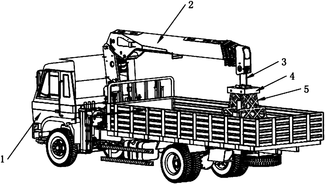
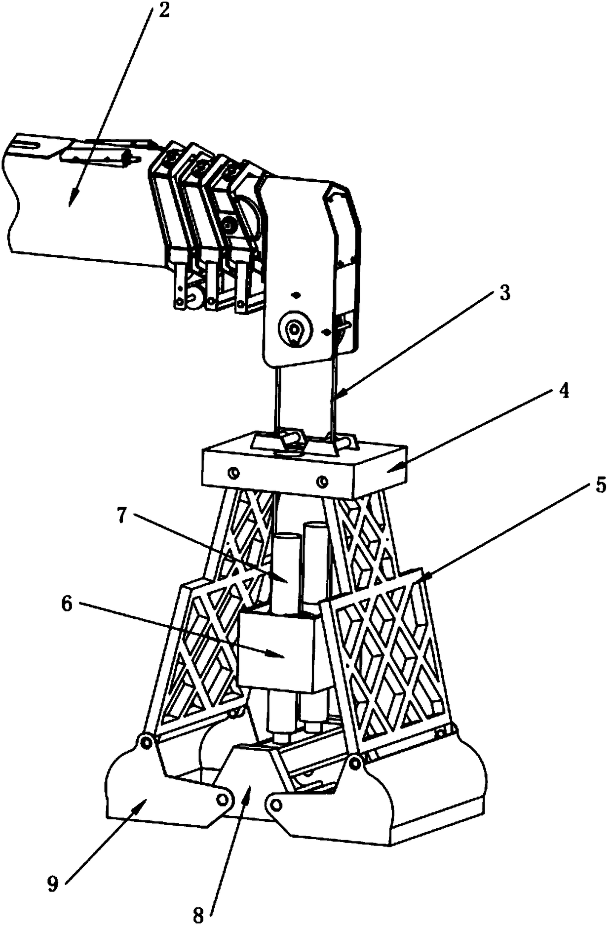
[0024] Such as figure 1 and figure 2 As shown, a dredging device and a crane with a dredging device include a car body 1 and a hoist 2, an upper frame body 4, a lower frame body 8, a petal-shaped hopper 9, a sliding frame 6, a truss connecting rod 5, and a sliding column 7 The winch 2 is installed on the chassis of the car body 1, the truss connecting rod 5 is provided with two and one of the common ends is respectively hinged on the upper frame body 4 in parallel, and the area between the two truss connecting rods 5 is used to form an installation space, The sliding column 7 is slidably arranged on the upper fr...


PUM


Abstract

The invention relates to a dredging device and a crane with the dredging device, and relates to the technical field of sludge cleaning equipment. The crane comprises a car body, a winch, an upper frame body, a lower frame body, petal-shaped hoppers, a sliding frame, truss connecting rods and a sliding column, wherein the winch is arranged on a chassis of the car body; the two truss connecting rodsare arranged; one common ends of the truss connecting rods are hinged onto the upper frame body in parallel; the sliding column is up-and-down slidably arranged on the upper frame body; the lower endpart of the sliding column is connected with the lower frame body; a limiting ring is arranged on the sliding column; the sliding frame slidably sleeves on a part, between the limiting ring and the lower frame body, of the sliding column; a pulley is rotatably arranged in the sliding frame; a steel wire rope is slidably arranged on the pulley and is further arranged on the winch; the two petal-shaped hoppers are oppositely arranged; one common ends of the two petal-shaped hoppers are hinged onto the lower frame body in parallel; and the other common ends of the two petal-shaped hoppers are hinged to the other common ends of the two truss connecting rods. The dredging device and the crane with the dredging device provided by the invention achieve the technical effects of wide dredging range and flexibility in dredging.

Description

technical field [0001] The invention relates to the technical field of sludge cleaning equipment, in particular to a dredging device and a crane with the dredging device. Background technique [0002] At present, the dredging work of urban life or industrial inspection wells is generally manual dredging and manual underground operations. The efficiency of sludge treatment is low, the labor intensity of workers is high, and the working environment is harsh; the existing dredging mechanism cannot flexibly dredge inside the inspection well. , can only work in a straight line perpendicular to the wellhead, so that the dredging range is small and the dredging is not complete; and during the dredging process, the weight of the grab bucket itself enters the dredging sludge, and human control will inevitably result in low dredging grabbing rate, When encountering branches or hard objects, it will cause problems such as incomplete dredging. Contents of the invention [0003] Aimin...

Claims


Application Information

Patent Timeline
IPC IPC(8): E02F5/28E02F3/60
CPCE02F3/60E02F5/28
Inventor 梁鹏郑昇皇甫熠涛
Owner 湖南铭狮机械有限公司
Why Eureka
Try Eureka