

Gear damage factor detecting method and device and wind turbine generator system
A damage factor and gear technology, applied in the field of mechanical non-destructive testing, can solve the problems of low gear damage accuracy, existing errors, gear damage factor errors, etc., and achieve the effect of improving accuracy and reducing errors
- Summary
- Abstract
- Description
- Claims
- Application Information
AI Technical Summary
Problems solved by technology
Method used
Image

Examples
Embodiment 1
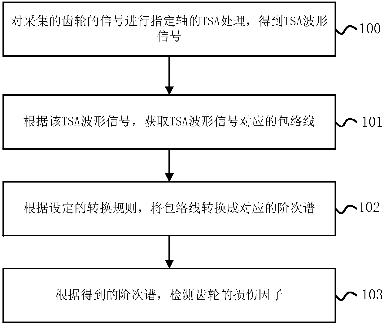
[0050] figure 1 The flow chart of Embodiment 1 of the detection method for the gear damage factor provided by the embodiment of the present invention is as follows: figure 1 As shown, the detection method of the gear damage factor in the embodiment of the present invention may specifically include the following steps:
[0051]100. Perform TSA processing of the designated axis on the collected gear signal to obtain a TSA waveform signal.
[0052] Generally speaking, after the tooth damage of the gear occurs, when it meshes with other gears, an additional shock-type vibration response signal will occur. Based on this phenomenon, in the prior art, the gear damage information can be extracted from the time domain, for example, the time domain kurtosis is used as an index to evaluate the damage degree of the gear. Alternatively, the gear damage information can be extracted from the order domain, for example, the sideband energy calculation method for the meshing frequency is used...
Embodiment 2
[0077] Figure 12The flow chart of the second embodiment of the detection method for the gear damage factor provided by the embodiment of the present invention, as Figure 12 As shown, the detection method of the gear damage factor provided by the embodiment of the present invention is in figure 1 The technical solutions of the present invention will be further described in more detail on the basis of the illustrated embodiments.
[0078] Such as Figure 12 As shown, the detection method of the gear damage factor provided by the embodiment of the present invention. Specifically, the following steps may be included:
[0079] 200. Collect the vibration response signal of the gear and the shaft speed signal of the known shaft of the gear.
[0080] For example, a sensor can be used to collect the vibration response signal of the gear, and the sensor in the embodiment of the present invention can include but not limited to: an acceleration sensor, a strain gauge, a thin film or...
example 1
[0104] Figure 13 It is the physical picture of the secondary high-speed pinion in the multi-stage fan gearbox, such as Figure 13 As shown, the secondary high-speed pinion and many other components are damaged. Figure 14 for Figure 13 Schematic diagram of the original vibration response signal corresponding to the middle and high speed pinion, Figure 15 for Figure 14 Schematic diagram of the waveform signal after the corresponding secondary high-speed axis TSA; Figure 14 As shown, due to the operating response signals of each component of the gearbox and the damage response signals of each damaged component, the damage response signal of the sub-high speed pinion is not obvious in the shaft cycle domain of the medium and high speed shaft. Such as Figure 15 As shown, in the Figure 14 Each signal in is processed by TSA technology to obtain the TSA waveform signal of the secondary high-speed pinion in the shaft period domain of the medium-high speed shaft.
[0105]...
PUM
 Abstract
Description
Claims
Application Information