
Double-clutch-type automatic gearbox transmission mechanism

A technology of automatic transmission and transmission mechanism, applied in the direction of transmission elements, transmission devices, vehicle gearboxes, etc., can solve the problems of accelerated wear of support bearings, influence of reverse power transmission, shortened service life of support bearings, etc. Well-arranged, large-scale design effect

Pending Publication Date: 2018-07-24
CHONGQING TSINGSHAN IND
View PDF6 Cites 3 Cited by
  • Summary
  • Abstract
  • Description
  • Claims
  • Application Information

AI Technical Summary

Problems solved by technology

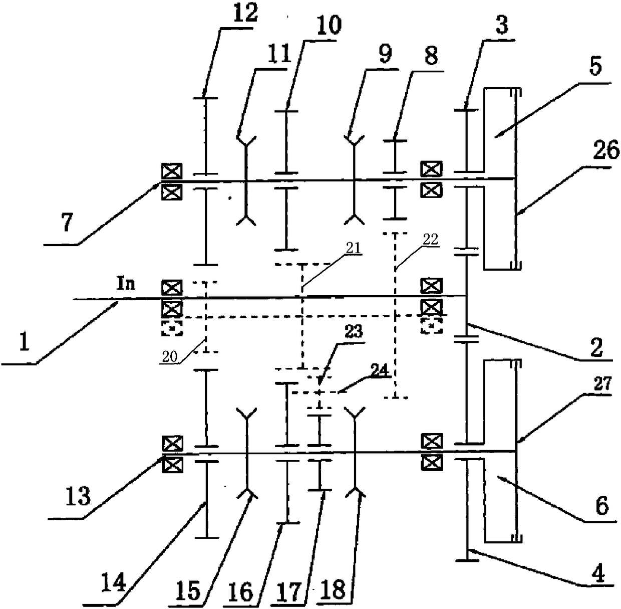
And the four-speed driving gear 14 will also be directly connected with the gear of the differential as the output gear simultaneously. The fourth and fifth gear driven gears 20 of the shaft are transmitted to the fourth gear driving gear 14, and then transmitted to the gears of the differential through the fourth gear driving gear 14, which will cause the fourth gear driving gear 14 and the supporting bearing of the second countershaft 13 to The wear is accelerated, and the service life of the supporting bearings of the fourth-speed driving gear 14 and the second countershaft 13 is shortened
At the same time, because the reverse gear 17 is arranged at the middle position of the second countershaft 13, since the reverse gear 17 bears a large moment at the middle position of the second countershaft 13, it will cause the second countershaft 13 to bend and deform during reverse gear. A large amount will seriously affect the power transmission of the reverse gear

Method used


Image

  • Double-clutch-type automatic gearbox transmission mechanism
  • Double-clutch-type automatic gearbox transmission mechanism
  • Double-clutch-type automatic gearbox transmission mechanism

Examples


Embodiment Construction

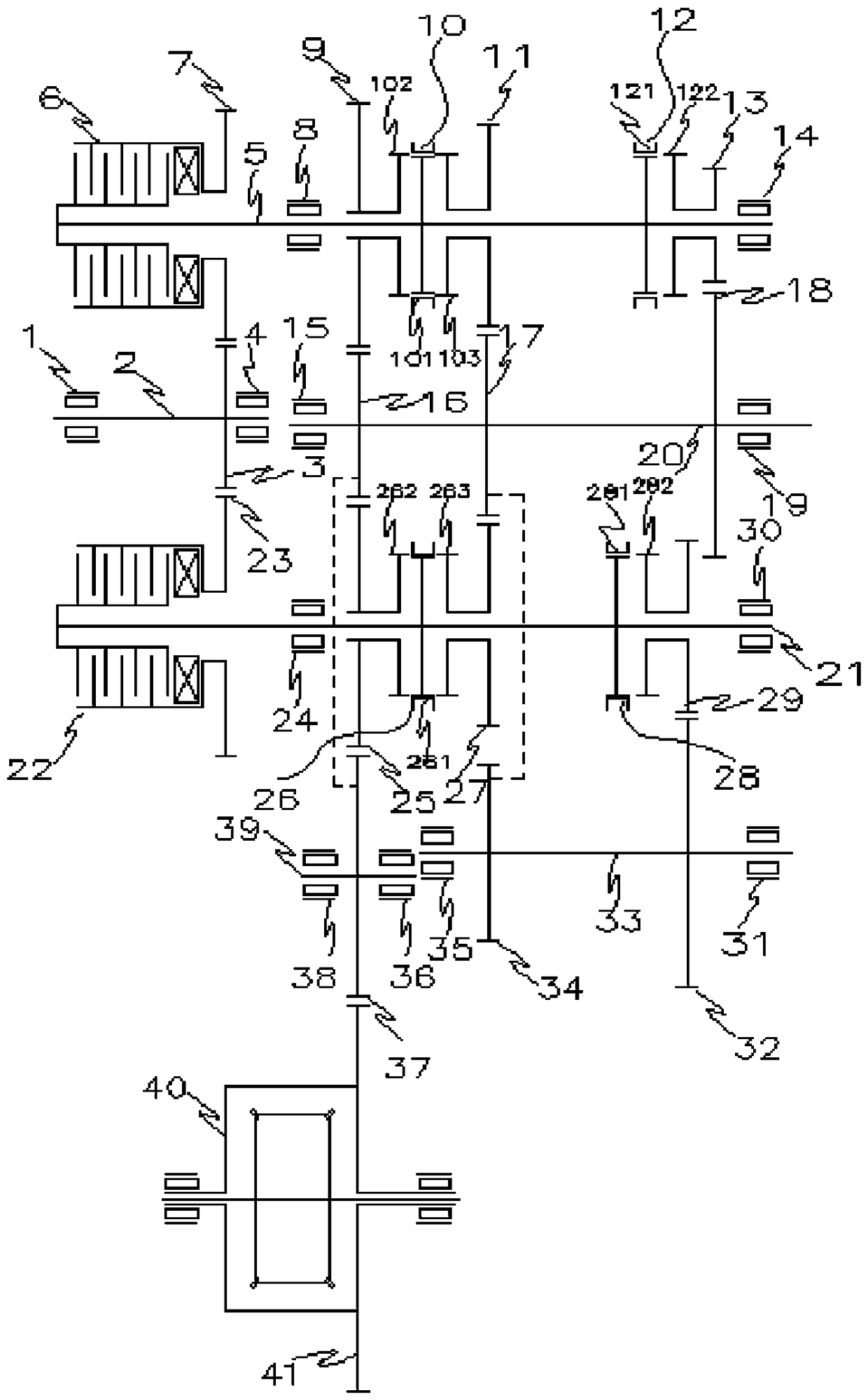
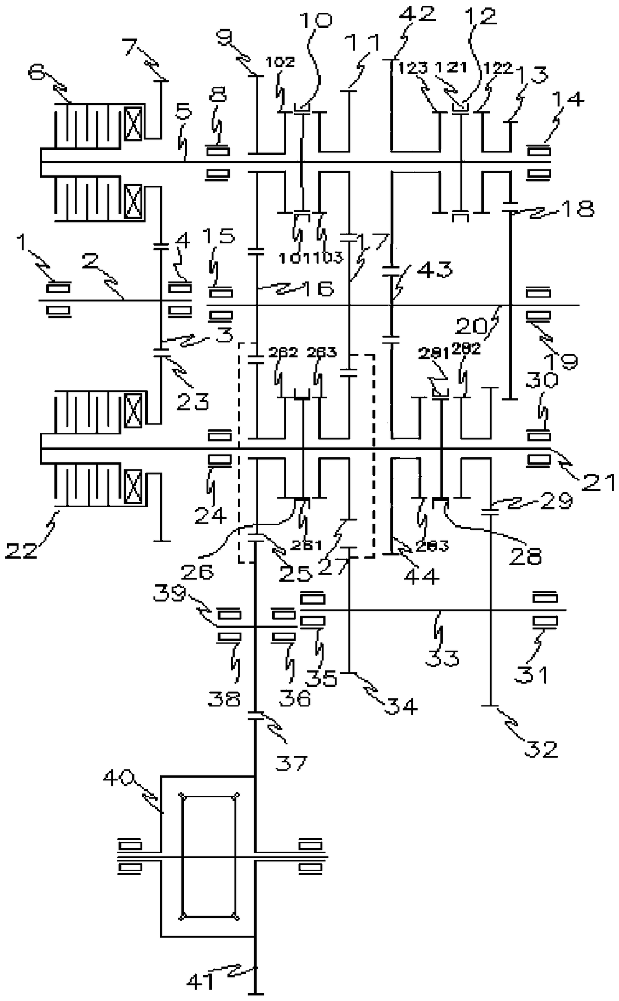
[0024] see Figure 1 to Figure 2 , a dual-clutch automatic transmission transmission mechanism, including an input shaft 2, a first countershaft 5, a second countershaft 21, and an intermediate shaft 20 supported by bearings and arranged in parallel, and the bearings supported are all arranged in the case of the transmission superior. The input shaft 2 meshes with the first clutch gear 7 and the second clutch gear 23 through a fixed input shaft gear 3, and the left end of the first countershaft 5 and the driven disc of the first clutch 6 are circumferentially fixed by splines connected, the left end of the second countershaft 21 is fixedly connected with the driven disk of the second clutch 22 through splines in the circumferential direction. The first clutch gear 7 and the second clutch gear 23 can be axially fixed and hollowly sleeved on the transmission case respectively. Or the first clutch gear 7 is axially and fixedly vacantly sleeved on the first countershaft 5, and t...


PUM


Abstract

The invention relates to a double-clutch-type automatic gearbox transmission mechanism. The double-clutch-type automatic gearbox transmission mechanism comprises an input shaft, a first auxiliary shaft, a second auxiliary shaft, an intermediate shaft, a reverse-gear shaft and an idle gear shaft which are supported through bearings and arranged in parallel; the first auxiliary shaft is sleeved witha five-gear drive gear, a three-gear drive gear and a one-gear drive gear; the second auxiliary shaft is sleeved with a four-gear drive gear, a two-gear drive gear and a reverse-gear gear; a first driven gear, a second driven gear and a third driven gear are fixedly arranged on the intermediate shaft; a reverse-gear drive gear and a reverse-gear driven gear are fixedly arranged on the reverse-gear shaft; and the first driven gear meshes with the five-gear drive gear, the four-gear drive gear and an output idle gear simultaneously, and the second driven gear meshes with the three-gear drive gear, the two-gear drive gear and the reverse-gear drive gear simultaneously. Power is input from an input shaft gear arranged on the input shaft and transmitted and output through the output idle geararranged on the idle gear shaft. According to the transmission mechanism, few gears mesh with one another simultaneously, the NVH performance of a transmission is good, and structural arrangement is good.

Description

technical field [0001] The invention relates to an automobile transmission, in particular to a transmission mechanism of a double-clutch automatic transmission. Background technique [0002] Dual-clutch automatic transmission is a kind of automatic transmission for automobiles. It not only inherits many advantages of manual transmission, but also solves the problem of cutting power and shifting existing in electronically controlled mechanical automatic transmissions. The power and shifting characteristics of the car are good. Fuel consumption and emissions are also reduced, and the economy of the car is also good. At present, the patent with the notification number of CN 101737462A discloses a dual-clutch transmission mechanism, such as image 3 As shown, the driving gear 10 of third gear on the first countershaft 7 in the mechanism, the driving gear 16 of second gear on the second countershaft 13 meshes with the driven gear 21 of second and third gears on the intermediate s...

Claims


Application Information

Patent Timeline
Patent Type & Authority Applications(China)
IPC IPC(8): F16H3/093F16H3/12F16H57/023
CPCF16H3/093F16H3/12F16H57/023F16H2200/0082F16H2200/0056F16H2200/2035F16H2003/0935
Inventor 胡敏彭飞王波张子川段红运严洪廖金龙丁成伟刁富强
Owner CHONGQING TSINGSHAN IND
Learn More