Eureka AIR delivers breakthrough ideas for toughest innovation challenges, trusted by R&D personnel around the world.

Improved valve filter

A technology of filtration equipment and valves, applied in the fields of filtration and separation, mechanical equipment, valve details, etc., can solve the problems of pipeline blockage, only rapid sewage discharge, and single function of sewage valve.

Inactive Publication Date: 2018-07-24
成都神智电子科技有限公司
View PDF0 Cites 0 Cited by
  • Summary
  • Abstract
  • Description
  • Claims
  • Application Information

AI Technical Summary

Problems solved by technology

[0006] The technical problem to be solved by the present invention is that the existing sewage valve has a single function and can only quickly discharge sewage, but cannot intercept solid waste, causing solid waste to accumulate downstream and cause pipeline blockage. The purpose is to provide an improved valve filtering device , carry out fixed garbage interception, and be able to clean up solid garbage

Method used


Image

  • Improved valve filter
  • Improved valve filter
  • Improved valve filter

Examples


Embodiment

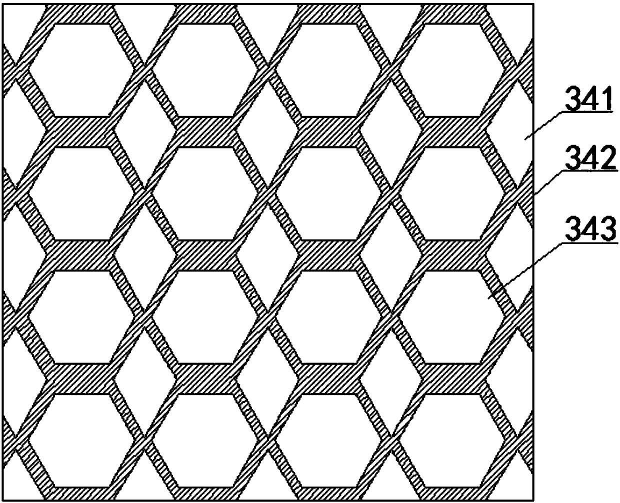
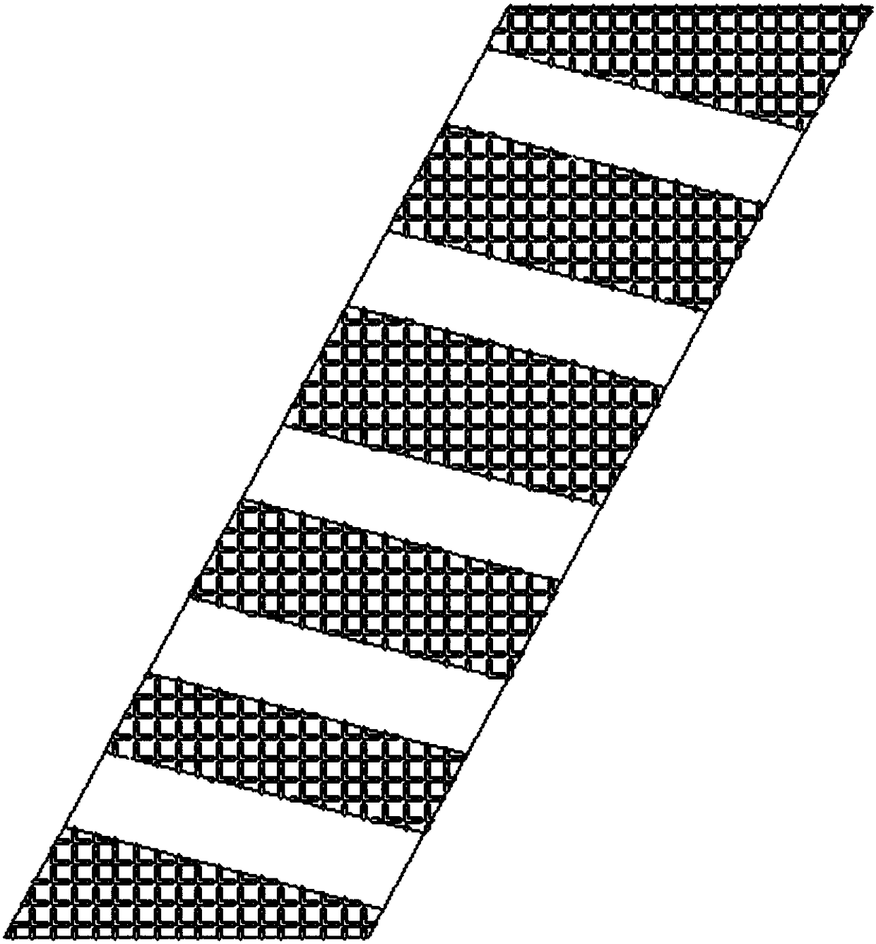
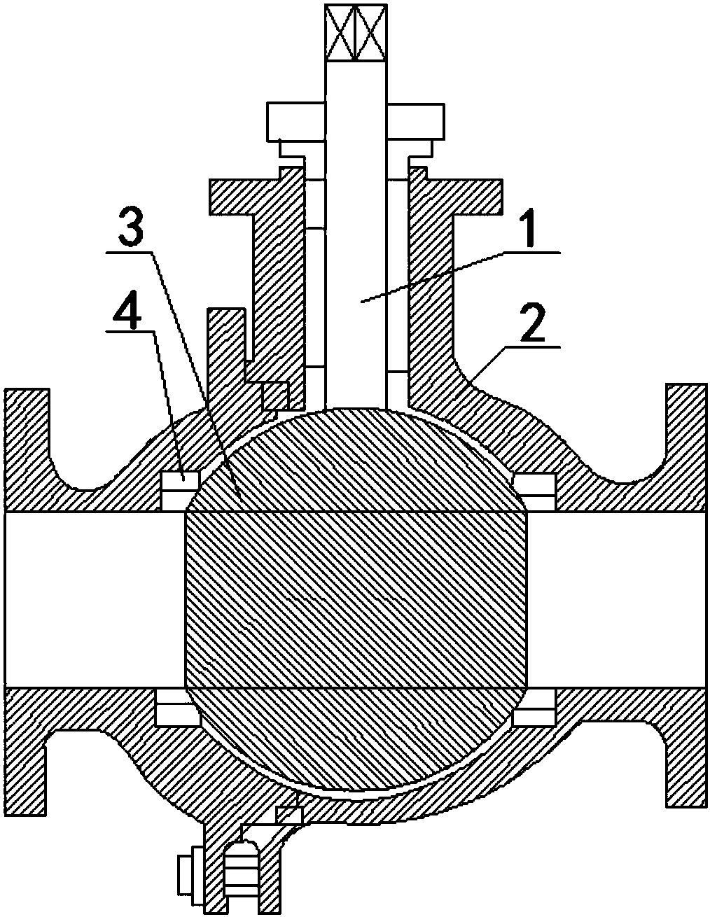
[0027] Such as Figure 2 to Figure 6 As shown, the sewage valve structure applicable to the present invention includes a valve stem 1, a valve body 2, a sphere 3, a sealing seat 4, a garbage discharge door panel 51, a sealing strip 52, and a handle 53. There is a channel in the middle of the valve body 2 in the horizontal direction. , the valve stem 1 is vertically arranged in the middle of the valve body 2 in the vertical direction, the ball 3 is arranged at the intersection of the downward extension line of the valve stem 1 and the channel; the sealing seat 4 is arranged at Between the sphere 3 and the valve body 2; the sphere 3 includes a sphere top 31, a sphere channel 32, a sphere bottom 33, and a sphere spacer 34, and the sphere top 31, the sphere channel 32, and the sphere bottom 33 are sequentially arranged from top to bottom , the bottom of the valve stem 1 is connected to the top 31 of the ball, and under the control of the valve stem 1, the ball channel 32 communica...


PUM

PropertyMeasurementUnit
thicknessaaaaaaaaaa

Abstract

The invention discloses an improved valve filter which comprises a separator body, rhomboid channels and polygon channels. The separator body is of a platy structure and has the thickness being 5mm to20mm; the rhomboid channels and the polygon channels are uniformly distributed on the separator body at intervals one by one; and an included angle is formed between a central axis of each polygon channel and a mid-perpendicular line of a plane on which the separator body is located. According to the improved valve filter provided by the invention, the separator body is arranged to be in an inclined shape; when sewage flows through the separator body, solid wastes in the sewage are impacted by a water flow and the separator body is inclined, so that the solid wastes can be firstly accumulatedon the upper side of the separator body at the beginning, only little solid wastes can be accumulated on the lower side, and the sewage can smoothly pass through the separator body; and meanwhile, the wastes and the sewage can be separated to a certain degree, the wastes move toward the right upper part of the separator body, and the sewage moves toward the right lower parts in the channels, so that the obstruction of the separator on the sewage is reduced.

Description

technical field [0001] The invention relates to a valve, in particular to an improved valve filtering device. Background technique [0002] A valve is a device used to control the direction, pressure, and flow of a fluid in a fluid system. It is a device that enables or stops the flow of media (liquid, gas, powder) in piping and equipment and controls its flow. [0003] The valve is a control component in the pipeline fluid conveying system, which is used to change the passage section and the flow direction of the medium, and has the functions of diversion, cut-off, throttling, check, diversion or overflow and pressure relief. Valves used for fluid control range from the simplest shut-off valve to various valves used in extremely complex automatic control systems. Valves for industrial pipelines. It can be used to control the flow of various types of fluids such as water, steam, oil, gas, mud, various corrosive media, liquid metals and radioactive fluids. The working press...

Claims


Application Information

Patent Timeline
Patent Type & Authority Applications(China)
IPC IPC(8): F16K5/06F16K5/08F16K27/06B01D35/04
CPCF16K5/0605B01D35/04F16K5/08F16K27/067
Inventor 王天鑫
Owner 成都神智电子科技有限公司
Why Eureka
Eureka Blog
Learn More