
Imaging moment calibration precision measurement method and system for spatial optical remote-sensing camera

A technology for space optical remote sensing and calibration accuracy, which is applied to measurement devices, photographic devices, instruments, etc., can solve the problem of lack of accuracy testing of optical remote sensing camera subsystems, and achieve the effect of simple testing method, strong adaptability and high accuracy.

Active Publication Date: 2018-07-24
BEIJING RES INST OF SPATIAL MECHANICAL & ELECTRICAL TECH
View PDF3 Cites 4 Cited by
  • Summary
  • Abstract
  • Description
  • Claims
  • Application Information

AI Technical Summary

Problems solved by technology

Lack of separate accuracy test for optical remote sensing camera subsystem

Method used


Image

  • Imaging moment calibration precision measurement method and system for spatial optical remote-sensing camera
  • Imaging moment calibration precision measurement method and system for spatial optical remote-sensing camera
  • Imaging moment calibration precision measurement method and system for spatial optical remote-sensing camera

Examples


Embodiment Construction

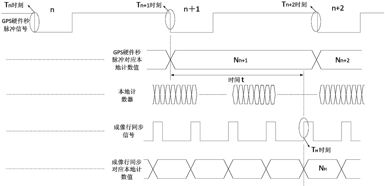
[0069] The visible light CCD spatial optical remote sensing camera imaging system outputs images in line image output mode, for example, the number of pixels in the CCD line array direction is 4096 (using 10-bit quantization, occupying 2 bytes), and the auxiliary data includes line fixed auxiliary data and frame auxiliary data Data, such as 20 bytes, then the composition of a row of images is auxiliary data + pixel image quantization data, the size is (20+4096*2)*8=65696bit, where the row of auxiliary data is entered into the local image of this row Imaging time. Set m lines of images to form a frame. M lines of images form a frame of images, and the frame auxiliary data contained in the image has "whole second time code". When the device receives the second pulse of the GPS hardware, it will add 1 to the stored data of the last full second at the same time. Therefore, the imaging time T of the current row of images = whole second time code + the local imaging time of the cu...


PUM


Abstract

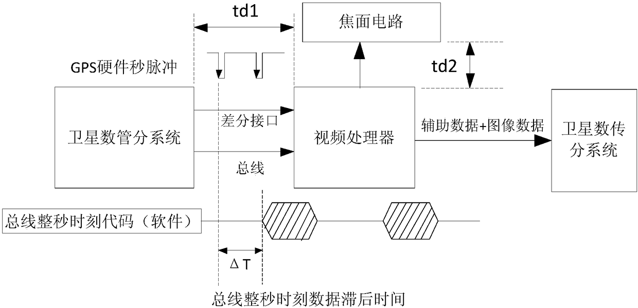
The invention discloses an imaging moment calibration precision measurement method and system for a spatial optical remote-sensing camera. The method comprises the following steps: calculating a relative time difference value of an imaging moment according to values recorded by a local counter when a GPS hardware pulse per second signal reaches a video processor and the video processor sends an imaging horizontal synchronizing signal, comparing the calculated relative time difference value of the imaging moment with a relative time difference value, measured by an oscilloscope, of the imagingmoment, and calibrating the imaging moment precision of the remote-sensing camera according to delay time of hardware. The imaging moment calibration precision measurement method disclosed by the invention is applicable to calibration of the imaging moment precision of all optical remote-sensing camera based on the GPS hardware pulse per second signal. The test method has the characteristics of being simple and convenient to operate, easy to standardize, and stable and reliable in test result, and has practical guiding significance for unified measurement of the imaging moment calibration precision. The method is high in applicability and favorable for building a unified measurement method standard, and analysis personnel can compare and analyze key technology indexes more easily.

Description

technical field [0001] The invention relates to a measurement method and system for calibrating accuracy of imaging time of space optical remote sensing cameras, and belongs to the field of aerospace remote sensing camera systems. Background technique [0002] The timing system of aerospace remote sensing surveying and mapping satellites is generally composed of a timing system and a timing system. The spaceborne remote sensing camera is used as a timing device, and the received second pulse signal is used as the timing reference of the camera subsystem. At the same time, the internal clock is used as the time counting signal. Accurately calculate the imaging moment of each row of images. Therefore, the time synchronization accuracy of the satellite system is determined by the system timing accuracy and punctuality accuracy: the timing accuracy is determined by the accuracy of the second pulse signal output by the GPS receiver; the punctuality accuracy is determined by the t...

Claims


Application Information

Patent Timeline
Patent Type & Authority Applications(China)
IPC IPC(8): G01C25/00G01C11/02
CPCG01C11/02G01C25/00
Inventor 郑君齐少凡李亮李坤张孝弘贺勍刘冰吴淞波于生全黄伟魏志勇王媛媛董建婷崔艳召张占东王旭明
Owner BEIJING RES INST OF SPATIAL MECHANICAL & ELECTRICAL TECH
Learn More