Overvoltage warning device and method based on pressure sensor and electrochromic device

An electrochromic device, pressure sensor technology, applied in the direction of measuring device, instrument, measuring force, etc., can solve problems such as unfavorable system stability, unfavorable system security, complicated control circuit, etc., achieve outstanding warning effect and long service life , the effect of simple control circuit

Active Publication Date: 2019-11-08
SHANGHAI MARITIME UNIVERSITY
View PDF7 Cites 0 Cited by
  • Summary
  • Abstract
  • Description
  • Claims
  • Application Information

AI Technical Summary

Problems solved by technology

[0002] Overvoltage warning devices have a very wide range of applications, especially in industrial production, the requirements for overvoltage warning devices are also very strict. At present, most of the devices used for warning in existing overvoltage warning devices use liquid crystal or digital tube display. Many functions and complex control circuits are not conducive to improving the stability of the system, the service life is short, and high voltage and current are required, which is not conducive to improving the safety of the system
[0003] Electrochromism refers to the phenomenon that the optical properties of the material (reflectivity, transmittance, absorption rate, etc.) undergo a stable and reversible color change under the action of an external electric field. Devices made of electrochromic materials are called electrochromic devices. Only a weak current and a voltage of about 1V can control discoloration, and the control is simple. At present, electrochromic devices have not been used in overvoltage warning devices.

Method used


Image

  • Overvoltage warning device and method based on pressure sensor and electrochromic device
  • Overvoltage warning device and method based on pressure sensor and electrochromic device
  • Overvoltage warning device and method based on pressure sensor and electrochromic device

Examples


Embodiment Construction

[0060] The present invention provides an overvoltage warning device and method based on a pressure sensor and an electrochromic device. In order to make the present invention more obvious and understandable, the present invention will be further described below in conjunction with the accompanying drawings and specific embodiments.

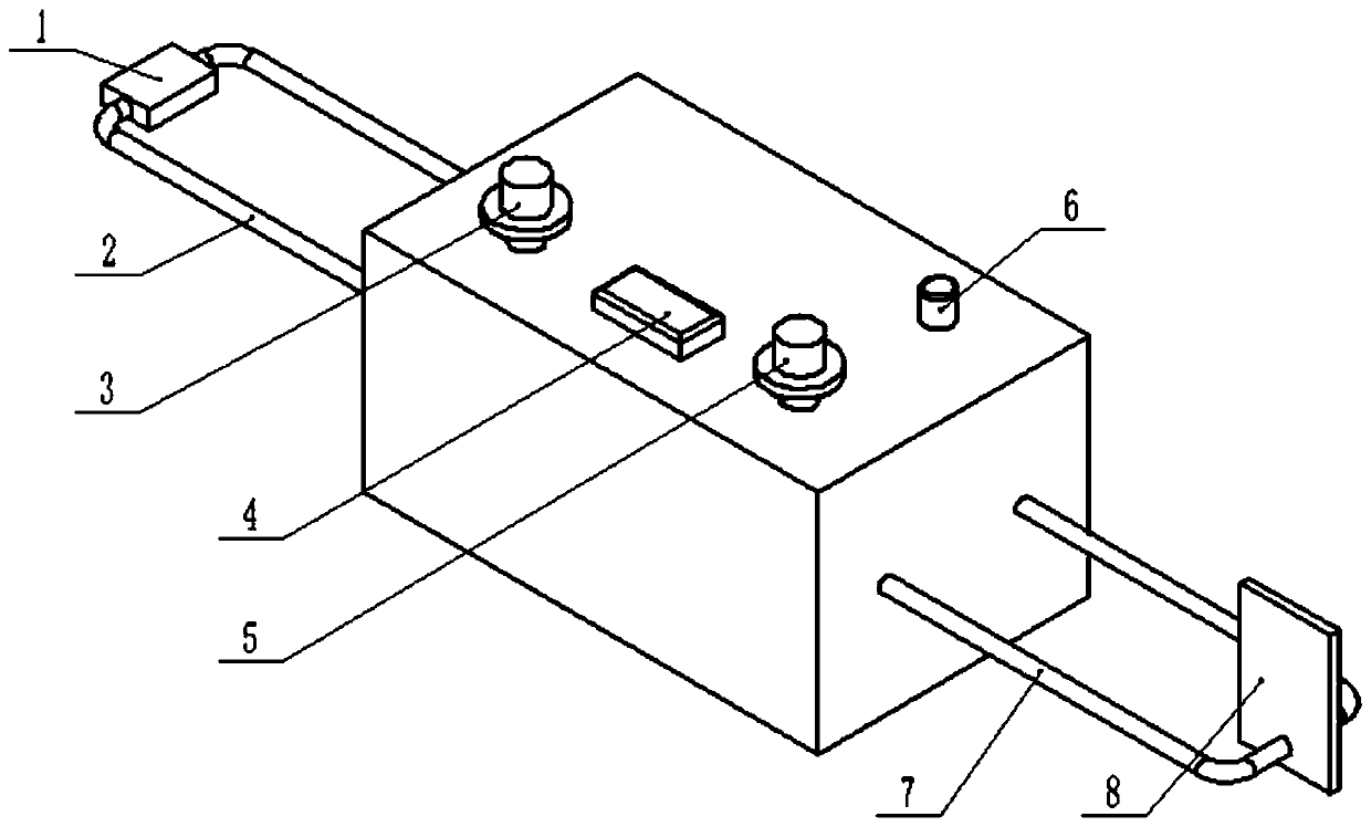
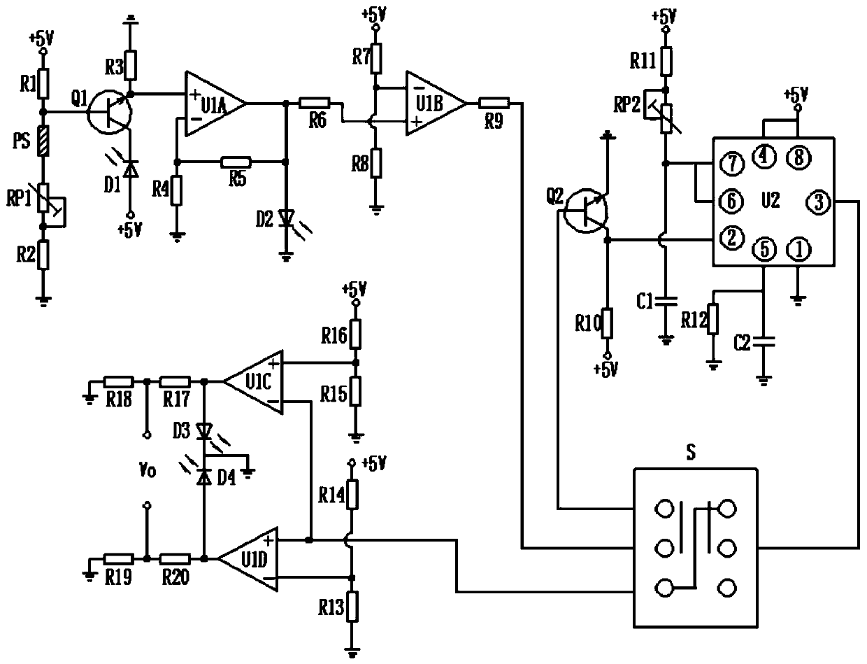
[0061] Such as figure 1 , figure 2 with image 3 Combined with the above, the overvoltage warning device based on the pressure sensor and electrochromic device of the present invention includes: a pressure sensor 1, a signal input line 2, a trigger pressure adjustment knob 3, a voltage display area 4, and a time delay Adjustment knob 5, delay trigger switch 6, output line 7, electrochromic device 8 and control circuit.

[0062] Exemplarily, the pressure sensor 1 is connected to the signal input line 2 . The signal input line 2 is from the pressure sensor PS in the control circuit (ie figure 1 The two ends of the pressure sensor 1) in the trig...


PUM


Abstract

The invention discloses an overvoltage warning device and method based on a pressure sensor and an electrochromic device. The overvoltage warning device comprises a control circuit, a signal input line, a trigger pressure adjustment knob, a voltage display area, a delay adjustment knob, a delay trigger switch, an output line and an electrochromic device, wherein the control circuit is provided with a pressure sensor, a first slide rheostat, a voltmeter, an NPN triode, a second slide rheostat and a switch; the signal input line is extracted from two ends of the pressure sensor; the trigger pressure adjustment knob is connected with the first slide rheostat; the voltage display area is connected with the voltmeter; the delay adjustment knob is connected with the second slide rheostat; the delay trigger switch is connected with the switch; the output line is extracted from an output end; and the electrochromic device is connected with two ends of the output line. When the overvoltage warning device is triggered by pressure, the output voltage is immediately reversed, and the electrochromic device is enabled to change in color; and when the pressure is below a trigger value, the outputvoltage is enabled to be reversed again, and the electrochromic device is enabled to return back to be original color. The overvoltage warning device is simpler and more stable in control circuit, less in consumed electric energy, safer and more environment-friendly and has a good warning effect.

Description

technical field [0001] The invention relates to the field of overvoltage warning equipment, in particular to an overvoltage warning device and method based on a pressure sensor and an electrochromic device. Background technique [0002] Overvoltage warning devices have a very wide range of applications, especially in industrial production, the requirements for overvoltage warning devices are also very strict. At present, most of the devices used for warning in existing overvoltage warning devices use liquid crystal or digital tube display. Many functions and complex control circuits are not conducive to improving the stability of the system, the service life is short, and high voltage and current are required, which is not conducive to improving the safety of the system. [0003] Electrochromism refers to the phenomenon that the optical properties of the material (reflectivity, transmittance, absorption rate, etc.) undergo a stable and reversible color change under the actio...

Claims


Application Information

Patent Timeline
Patent Type & Authority Patents(China)
IPC IPC(8): G01L1/20G01L1/00
CPCG01L1/005G01L1/20
Inventor 孙士斌唐成吉常雪婷常志杰
Owner SHANGHAI MARITIME UNIVERSITY
Why Eureka
Try Eureka