
Device for testing on thermal simulation test machine

A test device and thermal simulation technology, applied in measuring devices, using stable tension/pressure to test the strength of materials, instruments, etc., can solve the problems of inconsistent deformation temperature, large sample size, uneven temperature distribution, etc. Tendency to deformation, avoid uneven temperature distribution, easy assembly effect

Pending Publication Date: 2018-07-24
CITIC DICASTAL
View PDF0 Cites 3 Cited by
  • Summary
  • Abstract
  • Description
  • Claims
  • Application Information

AI Technical Summary

Problems solved by technology

This type of test method generally has three deficiencies: First, the strain that is neglected in the no-strain direction, although its value is small, actually exists, and the data obtained from the test cannot really describe the plane strain problem; second, due to the small size of the sample Large, there is an uneven temperature distribution when the sample is heated, which does not match the set deformation temperature, resulting in inaccurate test data; third, when the compression deformation is tested, the tangential deformation trend along the 45° direction is obvious, which is very important for the deformation test. Observation of sample tissue has a greater influence

Method used


Image

  • Device for testing on thermal simulation test machine
  • Device for testing on thermal simulation test machine
  • Device for testing on thermal simulation test machine

Examples


Embodiment 1

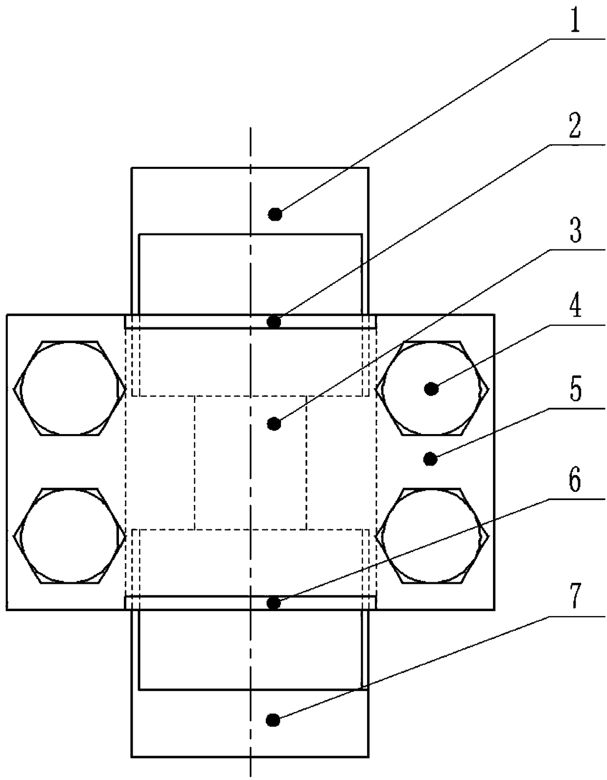
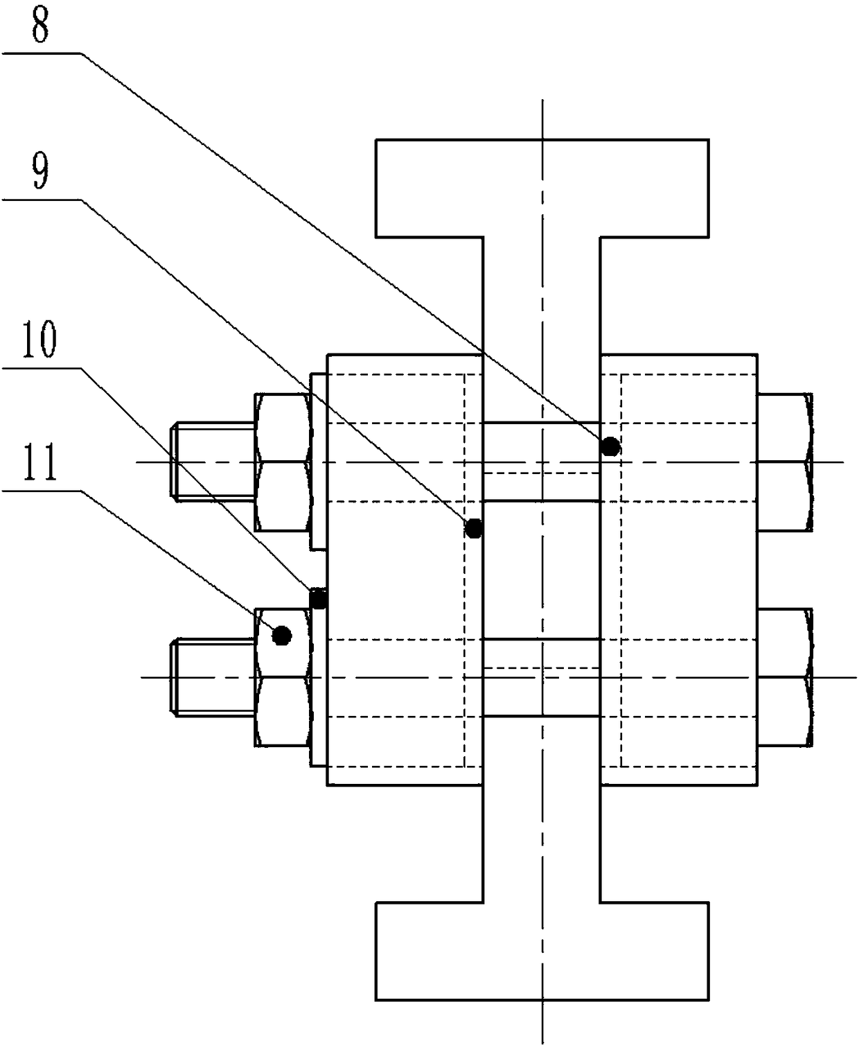
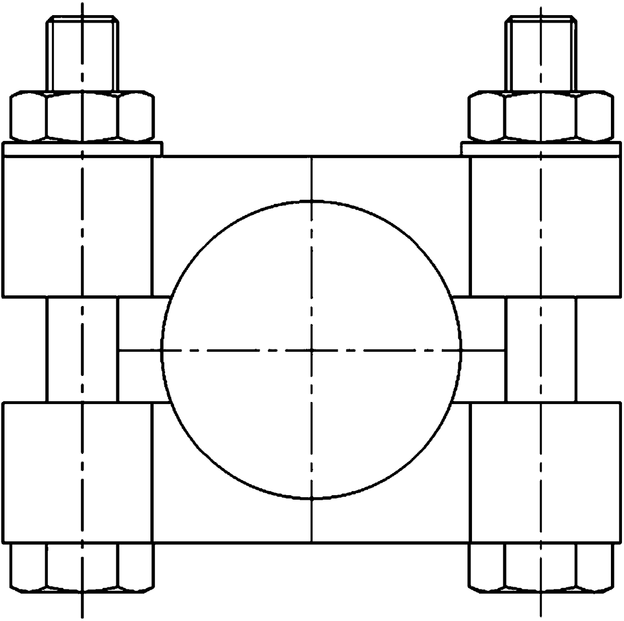
[0026] exist figure 1 , figure 2 , image 3 , Figure 4 , Figure 5 In the schematic diagram of the present invention shown, the test 3 is a cuboid, the upper indenter 1 and the lower indenter 7 made of YG8 hard alloy steel are located at both ends of the sample 3, respectively, and the upper indenter 1 and the lower indenter 7 The thickness of the flat plate part of the sample 3 should be equal to or smaller than the thickness of the sample 3, and the width of the flat plate part of the upper indenter 1 and the lower indenter 7 should be larger than that of the sample 3. The end pad A2, the end pad B6, the side pad A8, and the side pad B9 are all made of alumina ceramics with a thickness of about 1 mm; the pads are respectively placed in the corresponding grooves of the two fixing plates 5, and combined A fixed combination plate; the fixed plate 5 is made of high temperature alloy, and the depth of the groove is not more than 1mm; in order to ensure the convenience of pl...


PUM

PropertyMeasurementUnit
Gapaaaaaaaaaa

Abstract

The invention discloses a device for realizing a high temperature plane strain compression test on a thermal simulation test machine. High hardness profiled pressure heads are located at upper and lower ends of a sample. Insulation and high pressure-resistant side base plate and end base plate are respectively located in grooves in the end surface and inner side of a high-strength fixed plate. Thecombined fixed plates are respectively located in left and right sides of the sample. The combined fixed plates are fixed through four through holes of the fixed plate, high-strength bolts, washers and nuts to limit the deformation of the sample in the normal line of the fixed plate so that plane strain is formed. Compared with the existing test device, the device has the characteristics of uniform temperature distribution of the sample, high accuracy of the test data, small size, simple structure and convenient disassembling.

Description

technical field [0001] The invention relates to a device for realizing plane strain compression test of metal materials in a high temperature state. Background technique [0002] The plane strain problem is one of the typical deformation behaviors of metal materials, such as spinning deformation, rolling deformation, etc. There is no strain in the direction perpendicular to the strain plane during deformation. The conventional plane strain compression test was carried out on a Gleeble thermal simulation testing machine. The long and wide plate was used as the sample, and the narrow, long and narrow hammer was used as the compression anvil to test the stress-strain curves under different deformation parameters. This kind of test method generally has three shortcomings: first, the neglected strain in the unstrained direction, although its value is small but real, the data obtained from the test cannot really describe the plane strain problem; second, due to the relatively smal...

Claims


Application Information

Patent Timeline
IPC IPC(8): G01N3/02G01N3/18
CPCG01N3/02G01N3/18G01N2203/0682G01N2203/0226G01N2203/0019G01N3/08
Inventor 祁荣胜
Owner CITIC DICASTAL
Learn More