Continuous vacuum dip-painting production line

A technology of vacuum immersion and production line, which can be applied to conveyor objects, manufacturing motor generators, electrical components, etc., and can solve problems such as low work efficiency

Pending Publication Date: 2018-07-24
ZHONGSHAN KAIXUAN VACUUM SCI & TECH CO LTD
View PDF0 Cites 9 Cited by
  • Summary
  • Abstract
  • Description
  • Claims
  • Application Information

AI Technical Summary

Problems solved by technology

However, in the prior art, the devices used in each process are relatively scattered, and it is necessary to manually operate one or more special transfer tools to transfer the stators in a certain order between different devices in order to complete each process in sequence. less efficient

Method used


Image

  • Continuous vacuum dip-painting production line
  • Continuous vacuum dip-painting production line
  • Continuous vacuum dip-painting production line

Examples


Embodiment Construction

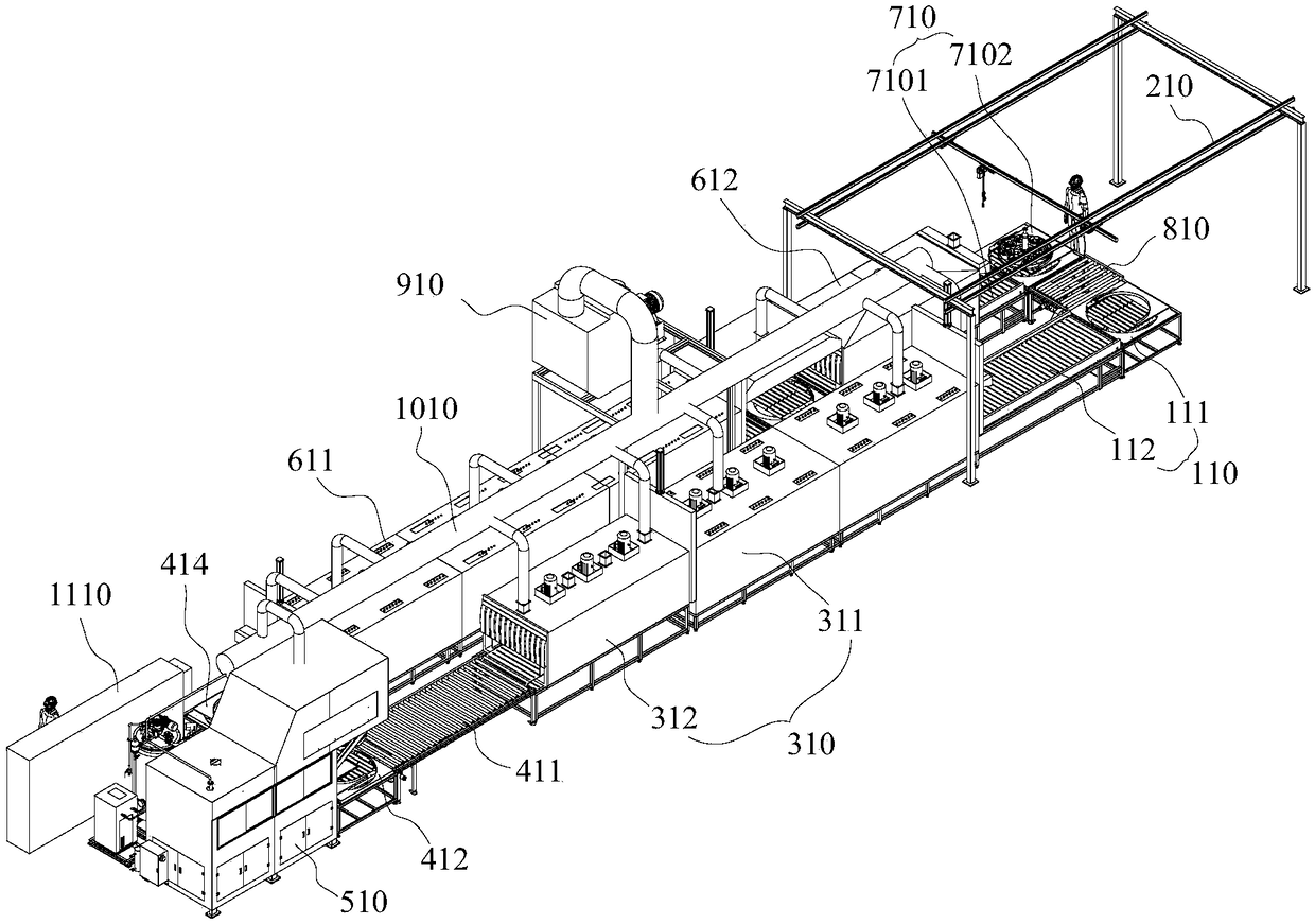
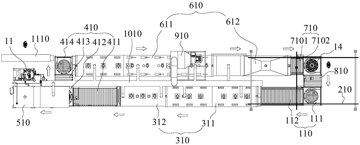
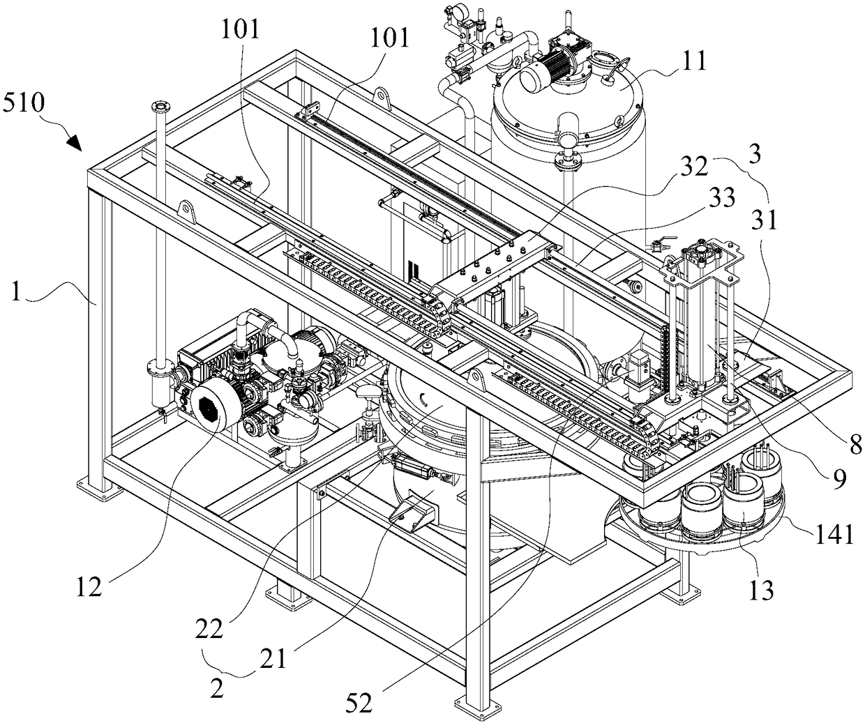
[0035] Example embodiments will now be described more fully with reference to the accompanying drawings. Example embodiments may, however, be embodied in many forms and should not be construed as limited to the embodiments set forth herein. Although relative terms such as "upper" and "lower" are used in this specification to describe the relative relationship of one component of an icon to another component, these terms are used in this specification only for convenience, for example, according to the drawings Directions for the example described. It will be appreciated that if the illustrated device is turned over so that it is upside down, then elements described as being "upper" will become elements that are "lower". Other relative terms, such as "top" and "bottom" also have similar meanings. When a structure is "on" another structure, it may mean that a structure is integrally formed on another structure, or that a structure is "directly" placed on another structure, or ...


PUM


Abstract

The invention discloses a continuous vacuum dip-painting production line. The continuous vacuum dip-painting production line comprises a crane device, a vacuum dip-coating system as well as a first conveying device, a preheating heat insulation device, a second conveying device, a cured cooling device and a third conveying device which are sequentially connected, wherein the preheating heat insulation device and the cured cooling device are arranged in parallel; the crane device is used for loading a stator on the first conveying device and unloading a stator of a hanging basket on the third conveying device; the vacuum dip-coating system is arranged on one side of the second conveying device and used for hoisting away the hanging basket on the second conveying device and putting the hanging basket subjected to dip-coating treatment back to the second conveying device.

Description

technical field [0001] The invention relates to a continuous vacuum impregnation production line. Background technique [0002] In the production process of the motor, the stator of the motor is usually dipped in paint to improve the insulation performance of the motor. The complete dipping process generally includes heating, dipping and cooling to form a stable insulation on the stator. Paint layer, and each process requires the use of special equipment to achieve. However, in the prior art, the devices used in each process are relatively scattered, and it is necessary to manually operate one or more special transfer tools to transfer the stators in a certain order between different devices in order to complete each process in sequence. less efficient. [0003] The above information disclosed in this Background section is only for enhancement of understanding of the background of the invention and therefore it may contain information that does not form the prior art that ...

Claims


Application Information

Patent Timeline
Patent Type & Authority Applications(China)
IPC IPC(8): H02K15/12B05C3/10B05C13/02B65G47/52B65G47/90
CPCH02K15/12B05C3/10B05C13/02B65G47/52B65G47/901
Inventor 郑庆强徐冬邝光照高峰李长安吴洽
Owner ZHONGSHAN KAIXUAN VACUUM SCI & TECH CO LTD
Why Eureka
Try Eureka