Solar photovoltaic assembly with cleaning function

A solar photovoltaic and component technology, applied in photovoltaic power generation, photovoltaic modules, electrical components, etc., can solve the problems of troublesome adjustment, easy to be contaminated with dust, inconvenient installation and transportation of components, and achieve reasonable and applicable structural design and improve light energy collection efficiency. , the effect of improving the convenience of transportation

Inactive Publication Date: 2018-07-24
吴自红
View PDF0 Cites 7 Cited by
  • Summary
  • Abstract
  • Description
  • Claims
  • Application Information

AI Technical Summary

Problems solved by technology

[0003] At present, most of the existing photovoltaic power generation modules are connected to the installation base by bolts through brackets, and the support of the brackets is poor. At the same time, it is inconvenient to install and transport various scattered components, and most of the existing photovoltaic panels have a fixed inclination angle, which is very troublesome to adjust. , does not have a cleaning function, and the photovoltaic panels are easily contaminated with dust when exposed to the outside for a long time, which is not conducive to prolonging their service life, and the efficiency of collecting light energy by photovoltaic panels covered with dust is greatly reduced

Method used


Image

  • Solar photovoltaic assembly with cleaning function
  • Solar photovoltaic assembly with cleaning function

Examples


Embodiment Construction

[0015] The following will clearly and completely describe the technical solutions in the embodiments of the present invention with reference to the accompanying drawings in the embodiments of the present invention. Obviously, the described embodiments are only some, not all, embodiments of the present invention. Based on the embodiments of the present invention, all other embodiments obtained by persons of ordinary skill in the art without making creative efforts belong to the protection scope of the present invention.

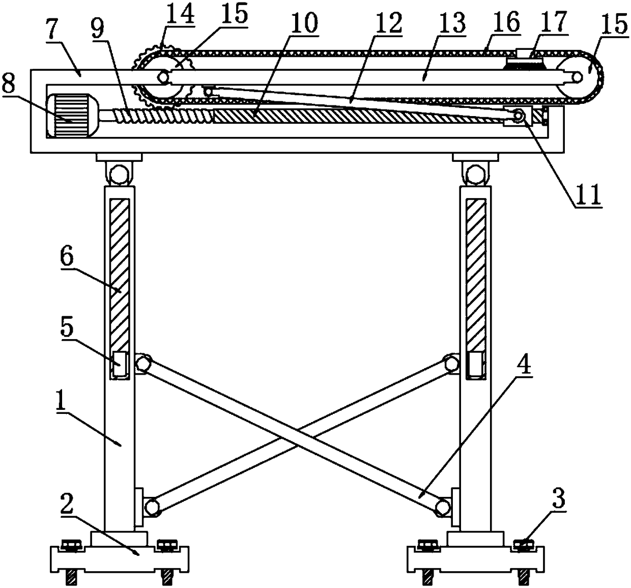
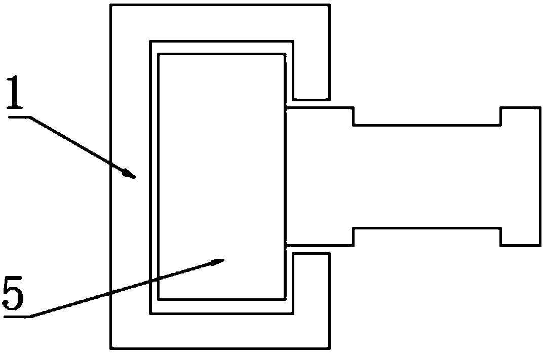
[0016] see Figure 1~2 , in an embodiment of the present invention, a solar photovoltaic module with a cleaning function, including a module body, a column 1, a movable rod 4, a drive motor 8, a threaded rod 10, a photovoltaic panel 13, a pulley 15 and a cleaning brush 17; The base 2 is provided on both sides of the lower part of the component body, and the four corners of the base 2 are respectively provided with threaded holes, and the threaded holes are int...


PUM


Abstract

The invention discloses a solar photovoltaic assembly with a cleaning function. The solar photovoltaic assembly with the cleaning function is characterized in that the upper end of a base is fixedly connected to a vertical column, wherein a guide groove is formed in the upper part of the vertical column, and a sliding block is connected into the guide groove in a sliding manner; the sliding blockis rotatably connected to the upper end of a movable rod; the right end of a worm is fixedly connected to a threaded rod, and the surface of the threaded rod is in thread connection with a sleeve; thesleeve is rotatably connected to the lower end of a connecting rod, and a photovoltaic plate is rotatably connected to the upper end of the connecting rod; a transverse frame is rotatably connected to the left end of the photovoltaic plate; a worm gear is engaged with the upper end of the worm and is rotatably connected to the transverse frame, and the worm gear is concentrically rotated with theleft end of the photovoltaic plate; the worm gear is fixedly connected to a belt wheel; a cleaning brush is fixedly connected to the upper part of a transmission belt. According to the photovoltaic assembly, the movable rod is used for supplying supporting force to the middle part of the vertical column, so that the supporting effect is improved, and the convenience of storing and conveying is ensured; in addition, the rotating threaded rod is capable of driving the sleeve to move leftwards and rightwards, and thus the photovoltaic plate can swing to adjust the inclination angle, and the wormgear is driven to rotate through the worm during angle adjusting, and the rotating worm gear drives the transmission belt to roll to enable the cleaning brush to move to clean the surface of the photovoltaic plate.

Description

technical field [0001] The invention relates to a new energy device, in particular to a solar photovoltaic module with a cleaning function. Background technique [0002] Photovoltaic power generation is a technology that directly converts light energy into electrical energy by using the photovoltaic effect of the semiconductor interface. The main principle of photovoltaic power generation is the photoelectric effect of semiconductors. When a photon irradiates a metal, its energy can be completely absorbed by an electron in the metal. The energy absorbed by the electron is large enough to overcome the internal gravitational force of the metal to do work, escape from the metal surface, and become a photoelectron. [0003] At present, most of the existing photovoltaic power generation modules are connected to the installation base by bolts through brackets. The support of the brackets is poor. At the same time, it is inconvenient to install and transport various scattered compo...

Claims


Application Information

Patent Timeline
Patent Type & Authority Applications(China)
IPC IPC(8): H02S40/10
CPCH02S40/10Y02E10/50
Inventor 吴自红
Owner 吴自红
Why Eureka
Try Eureka