Splicing load carrying rack

A load-carrying rack and splicing technology, which is applied in the direction of mobile frames, engine frames, and rod connections, can solve the problems of inability to carry out mass production and large-scale stocking, large restrictions on the demand side, and inconvenient storage and transportation. Achieve the effects of improving transportation convenience, wide application range, and simplifying the steps of material preparation

Pending Publication Date: 2018-11-23
JIANGSU COWAIN AUTOMATION TECH
View PDF9 Cites 2 Cited by
  • Summary
  • Abstract
  • Description
  • Claims
  • Application Information

AI Technical Summary

Problems solved by technology

[0003] 1. Specific tools are required for positioning, adjustment and welding, and most of them are produced by professional manufacturers, which has great restrictions on the demand side;
[0004] 2. The welding frame needs to go through processes such as pipe cutting, welding, grinding and derusting, and spraying, with many processes and a long production cycle;
[0005] 3. After the welding frame is formed, especially after spraying, there is no room for modification, and it cannot be flexibly changed according to the design requirements
[0006] 4. Considering the third point and the different size requirements of the demand side, mass production and mass stocking cannot be carried out, which makes the cost of a single product high;
[0007] 5. The welding frame occupies a large space after forming, which will cause inconvenience to storage and transportation, and needs to be improved

Method used


Image

  • Splicing load carrying rack
  • Splicing load carrying rack
  • Splicing load carrying rack

Examples


Embodiment Construction

[0024] The following will clearly and completely describe the technical solutions in the embodiments of the present invention. Obviously, the described embodiments are only some of the embodiments of the present invention, rather than all the embodiments. Based on the embodiments of the present invention, all other embodiments obtained by persons of ordinary skill in the art without making creative efforts belong to the protection scope of the present invention.

[0025] see Figure 1~Figure 3 , the embodiment of the present invention includes:
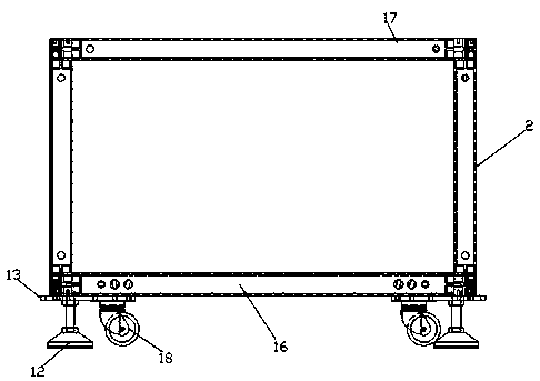
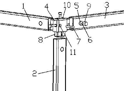
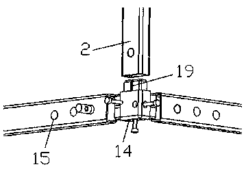
[0026] A spliced ​​load frame, comprising: an upper frame 17, a lower frame 16 and a Z-axis connecting pipe 2, the upper frame 17 is located directly above the lower frame 16, and the upper frame 17 and the lower frame 16 respectively include four Pipe joint 4, two X-axis connecting pipes 1 and two Y-axis connecting pipes 3, the two Y-axis connecting pipes 3 are arranged between the ends of two parallel X-axis connecting pipes 1 to f...


PUM


Abstract

The invention discloses a splicing load carrying rack, comprising an upper box, a lower box and Z-axis connecting pipes, wherein each of the upper box and the lower box comprises four pipe joints, twoX-axis connecting pipes and two Y-axis connecting pipes, Z-axis connecting pipes are vertically arranged between the corresponding pipe joints of the upper and lower boxes, the pipe joints are provided with inserting blocks extending into the X-axis connecting pipes, the Y-axis connecting pipes and the Z-axis connecting pipes correspondingly, each pipe joint is provided with three cylindrical counterbores extending along the length directions of the X-axis connecting pipes, the Y-axis connecting pipes and the Z-axis connecting pipes into the corresponding inserting blocks, and the cylindricalcounterbores are internally provided with screws connected to the corresponding connecting members. In the manner, the splicing load carrying rack has a stable structure and flexible adjustment, minimizes processing steps, reduces requirements on assembly technology, and is convenient for storage and transportation.

Description

technical field [0001] The invention relates to the technical field of assembled racks, in particular to a spliced ​​load rack. Background technique [0002] At present, the under-load racks in the field of automation are mostly welded by rectangular tubes, which have the following disadvantages: [0003] 1. Specific tools are required for positioning, adjustment and welding, and most of them are produced by professional manufacturers, which has great restrictions on the demand side; [0004] 2. The welding frame needs to go through processes such as pipe cutting, welding, grinding and derusting, and spraying, with many processes and a long production cycle; [0005] 3. After the welding frame is formed, especially after spraying, there is no room for modification, and it cannot be flexibly changed according to the design requirements. [0006] 4. Considering the third point and the different size requirements of the demand side, mass production and mass stocking cannot be...

Claims


Application Information

Patent Timeline
Patent Type & Authority Applications(China)
IPC IPC(8): F16M1/00F16M3/00F16B7/18
CPCF16B7/185F16M1/00F16M3/00
Inventor 段徽庆韩鹏刘进严佳晟
Owner JIANGSU COWAIN AUTOMATION TECH
Why Eureka
Try Eureka