Punching device

A punching device and plate placement technology, which is applied to the feeding device, positioning device, storage device, etc., can solve the problems of poor clamping effect of parts, affecting the size of punching holes, etc., so as to achieve simple and efficient clamping process and extended use. The effect of longevity and simple operation

Active Publication Date: 2018-07-27
CHONGQING JIANAN IND & TRADE
View PDF9 Cites 1 Cited by
  • Summary
  • Abstract
  • Description
  • Claims
  • Application Information

AI Technical Summary

Problems solved by technology

[0006] The purpose of the present invention is to provide a punching device to solve the problem that the clamping effect on the parts is not good and the size of the punching holes is affected when the parts are punched.

Method used


Image

  • Punching device
  • Punching device
  • Punching device

Examples


Embodiment Construction

[0020] The present invention will be described in further detail below by means of specific embodiments:

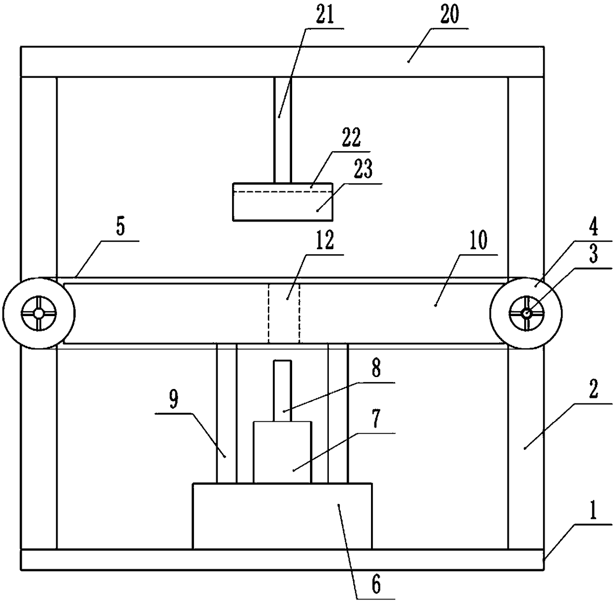
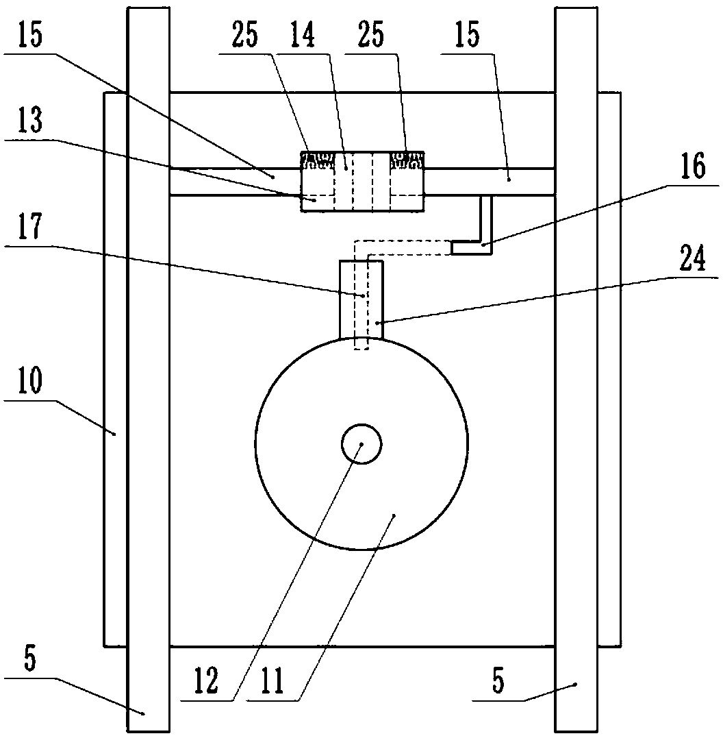
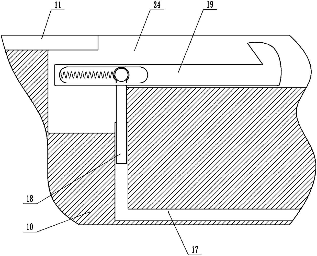
[0021] The reference signs in the drawings of the description include: base 1, pillar 2, transverse shaft 3, pulley 4, conveyor belt 5, support table 6, cylinder 7, punch 8, support rod 9, placement plate 10, placement slot 11, through Hole 12, sleeve 13, first electromagnet 14, ejector rod 15, push rod 16, cavity structure 17, slider 18, buckle rod 19, beam 20, pole 21, second electromagnet 22, collection box 23, the first groove 24, the first spring 25.

[0022] Such as figure 1 As shown, the punching device includes a base 1 and a motor that rotates intermittently. The motor is controlled by a controller to rotate intermittently. The middle part of each pillar 2 is provided with a shaft hole respectively, bearing housings are installed on both sides of the shaft hole, a bearing is installed in the bearing housing, and a horizontal shaft 3 is installed in the bearing;...


PUM


Abstract

The invention belongs to the technical field of punching equipment and particularly discloses a punching device. The punching device comprises a base, wherein a pillar, a first groove, a bayonet rod,a cavity structure, a push rod and a slider are arranged on the base; a cross shaft is arranged on the pillar; belt pulleys are arranged on the cross shaft; conveying belts are connected between beltpulleys on the same sides of the pillar; a support table is arranged in the middle of the base; an air cylinder is arranged on the support table; a punch is arranged at the upper end of a piston rod of the air cylinder; a support rod is arranged on a workbench; a storage plate is arranged on the support rod; a through hole is formed in the storage plate; a sleeve is arranged on the storage plate;an electromagnet and an ejector rod are arranged in the sleeve; the push rod is connected with the ejector rod. The punching device is mainly used for part punching and solves the problem that the part punching size is affected by poor part clamping effect.

Description

technical field [0001] The invention belongs to the technical field of punching equipment, and specifically discloses a punching device. Background technique [0002] The parts used on mechanical equipment can be quickly installed on the equipment by punching holes on the parts. By punching holes on the parts, not only the quality of the parts is reduced, but also the installation is convenient. [0003] When punching parts, there will be waste left by punching. Collecting waste artificially is inefficient and time-consuming. Artificially collecting waste left by punching is labor-intensive and increases labor costs. [0004] In view of the above problems, Chinese patent CN105772562B discloses a punching machine, which includes: a chassis, a stamping cylinder and a telescopic cylinder are arranged on the chassis, a punch is arranged on the top of the stamping cylinder, and a conveyor belt and a transmission plate are arranged above the stamping cylinder. The telescopic oil ...

Claims


Application Information

Patent Timeline
IPC IPC(8): B21D43/00B21D43/12B21D28/24
CPCB21D28/24B21D43/003B21D43/12
Inventor 肖福禄
Owner CHONGQING JIANAN IND & TRADE
Why Eureka
Try Eureka