Copper wire cutting equipment having propelling function

A technology of cutting equipment and copper wire, which is applied in the field of copper wire cutting equipment with a propulsion function, and can solve the problems of different lengths of copper wires, economic losses of enterprises, slipping, etc.

Inactive Publication Date: 2018-07-27
HUIAN WEIKE ELECTRONICS TECH CO LTD
View PDF6 Cites 9 Cited by
  • Summary
  • Abstract
  • Description
  • Claims
  • Application Information

AI Technical Summary

Problems solved by technology

[0002] In the current copper wire cutting method, the length of the copper wire after cutting is different, so the size and length of the copper nails made are also inconsistent, so there will be a large number of defective products, which will bring significant economic losses to the enterprise, and the existing Copper wire is usually placed in a roll, so when the pay-off roller is released, the straightness of the copper wire is very low, resulting in different lengths of the copper wire after cutting, which leads to the quality of the copper nail processing cannot be guaranteed; in addition, In the existing technology, the movement of the copper wire is realized by using the pulling roller, but it is easy to slip, resulting in insufficient actual cutting length, which affects the use effect

Method used


Image

  • Copper wire cutting equipment having propelling function
  • Copper wire cutting equipment having propelling function
  • Copper wire cutting equipment having propelling function

Examples


Embodiment Construction

[0015] The following will clearly and completely describe the technical solutions in the embodiments of the present invention with reference to the accompanying drawings in the embodiments of the present invention. Obviously, the described embodiments are only some, not all, embodiments of the present invention. Based on the embodiments of the present invention, all other embodiments obtained by persons of ordinary skill in the art without making creative efforts belong to the protection scope of the present invention.

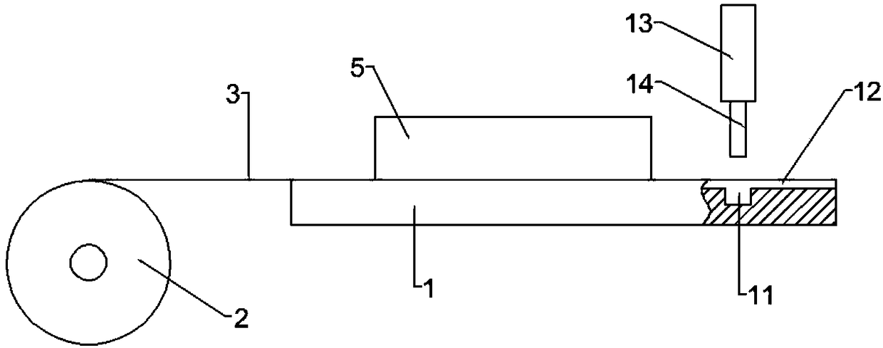
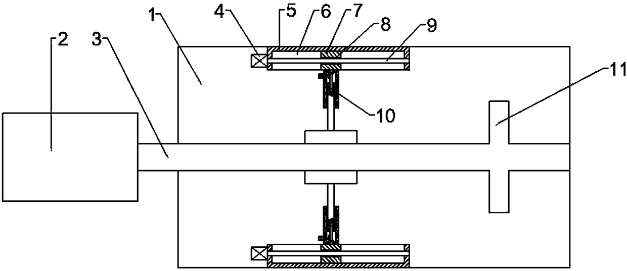
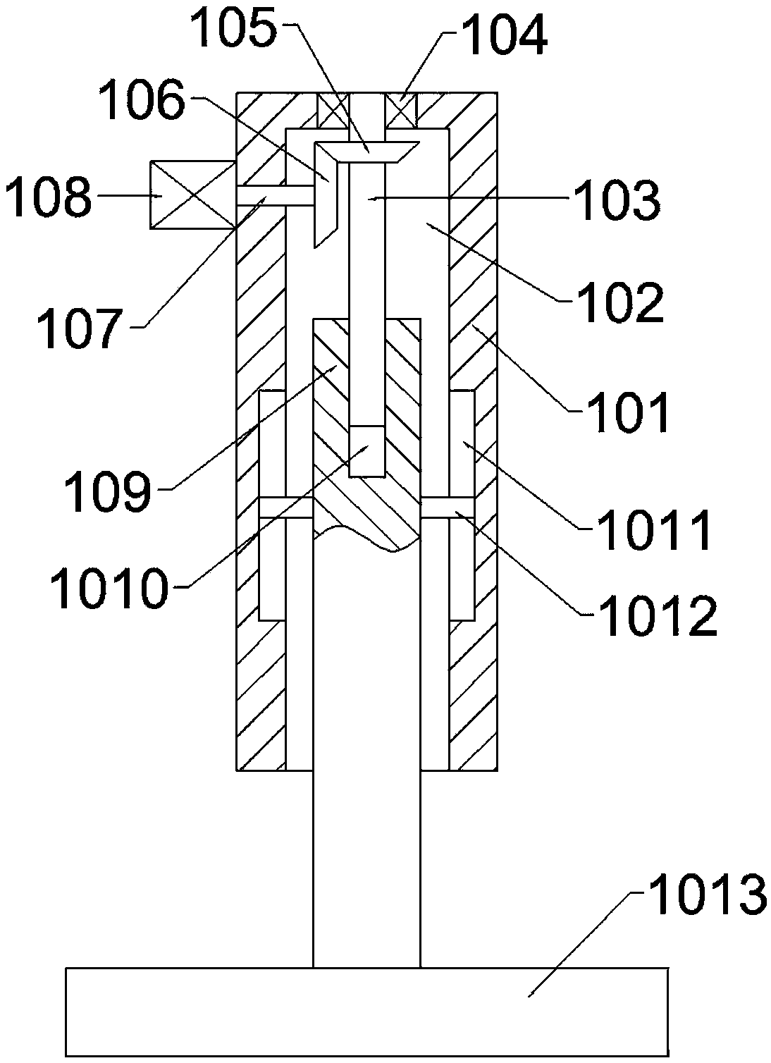
[0016] see Figure 1-Figure 3 , in an embodiment of the present invention, a copper wire cutting device with a propulsion function includes a workbench 1 and a pay-off roller 2, a guide groove 12 is opened on the upper surface of the workbench 1, and a copper wire 3 is placed in the guide groove 12 , the left end of the copper wire 3 is wound on the pay-off roller 2, the copper wire 3 can move in the guide groove 12, the guide groove 12 not only has a certain ...


PUM


Abstract

The invention provides copper wire cutting equipment having a propelling function. The copper wire cutting equipment comprises a worktable and a wire unwinding roller; the upper surface of the worktable is provided with a guide groove; a copper wire is placed inside the guide groove; the left end of the copper wire is intertwined on the wire unwinding roller; the parts, positioned at the front andrear sides of the guide groove, of the worktable are symmetrically and fixedly connected with two mounting columns; each mounting column is in a cuboid shape and is provided with a moving groove; each moving groove is internally provided with a moving block; and each moving block is provided with a threaded through hole. The copper wire cutting equipment provided by the invention has the beneficial effects that the copper wire can move inside the guide groove; the guide groove plays a certain guiding role on the copper wire and can also be used for straightening the pre-bent copper wire; a second motor is used for driving a rotating shaft to rotate; the rotating shaft is used for driving a second bevel gear to rotate; the second bevel gear is used for driving a first bevel gear to rotate;the first bevel gear is used for driving a vertical threaded rod to rotate; an extending rod matched with the vertical threaded rod extends out of a groove so as to drive a clamping plate to clamp and fix the copper wire, and thus the copper wire can be conveniently driven to move.

Description

technical field [0001] The invention relates to the technical field of copper wire processing, in particular to a copper wire cutting device with a propulsion function. Background technique [0002] In the current copper wire cutting method, the lengths of the copper wires after cutting are different, so the size and length of the copper nails are also inconsistent, so there will be a large number of defective products, which will bring significant economic losses to the enterprise, and the existing Copper wires are usually placed in rolls, so when the pay-off roller is released, the straightness of the copper wires is very low, resulting in different lengths of the copper wires after cutting, resulting in the quality of copper nail processing cannot be guaranteed; in addition, In the prior art, the movement of the copper wire is realized by using the pulling roller, but it is easy to slip, resulting in insufficient actual cutting length, which affects the use effect. Cont...

Claims


Application Information

Patent Timeline
Patent Type & Authority Applications(China)
IPC IPC(8): B21F11/00B21F1/02B21F23/00
Inventor 王少平
Owner HUIAN WEIKE ELECTRONICS TECH CO LTD
Why Eureka
Try Eureka