Thin sheet conveying device

A conveying device and plate technology, applied in the direction of conveyors, conveyor objects, transportation and packaging, etc., can solve the problems of complex equipment structure, increased cost, and inability to accurately position materials, so as to save the limit mechanism and save production costs , the effect of precise loading and unloading

Inactive Publication Date: 2018-07-27
YUNHEMAN WALKER TOYS CO LTD
View PDF1 Cites 5 Cited by
  • Summary
  • Abstract
  • Description
  • Claims
  • Application Information

AI Technical Summary

Problems solved by technology

[0002] Most of the existing conveying devices for loading and unloading thin plates use conveyor belts. During the conveying process, it is difficult to limit the way the thin plates are placed, and it is impossible to achieve accurate loading. Even if it can be accurately loaded, it must be Setting a limit mechanism on the conveyor belt makes the equipment structure too complicated and increases the cost
[0003] Patent No. CN204198040 is a special conveyor for thin plates, including two left and right conveying units, which are characterized in that: the left and right conveying units are composed of two runners and a plurality of uniformly spaced conveying belts Composition, the two runners are respectively located at the left and right ends of the conveyor belt, the right runner of the left conveying unit is located at the right end of the left runner of the right conveying unit, the belt on the left conveying unit and the belt on the right conveying unit Staggered arrangement, unable to accurately locate the material

Method used


Image

  • Thin sheet conveying device
  • Thin sheet conveying device
  • Thin sheet conveying device

Examples


Embodiment Construction

[0025] Below in conjunction with accompanying drawing and embodiment of description, specific embodiment of the present invention is described in further detail:

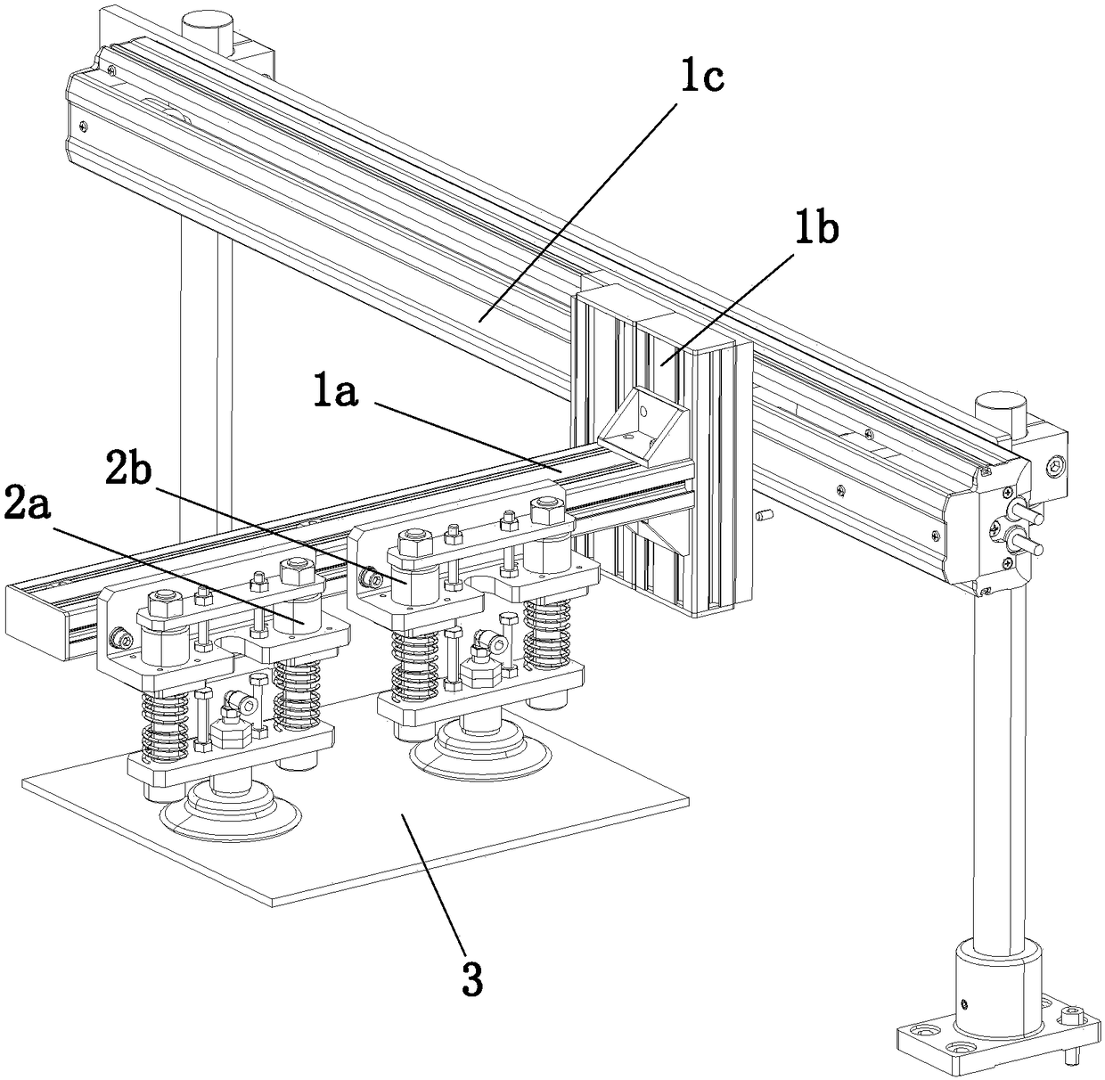
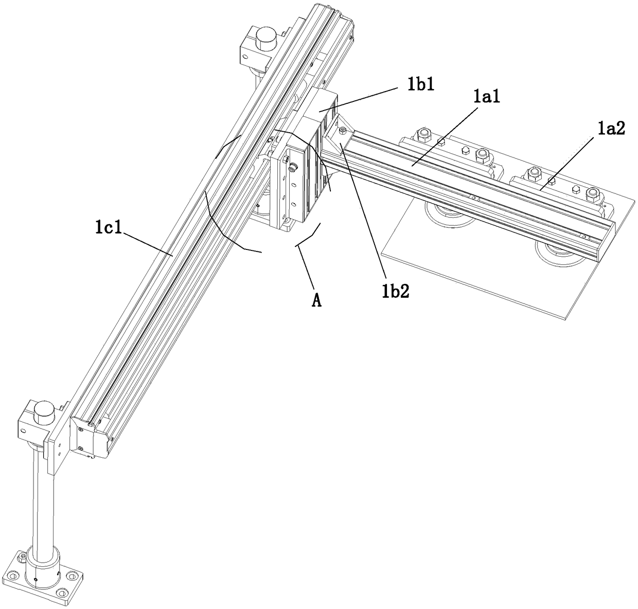
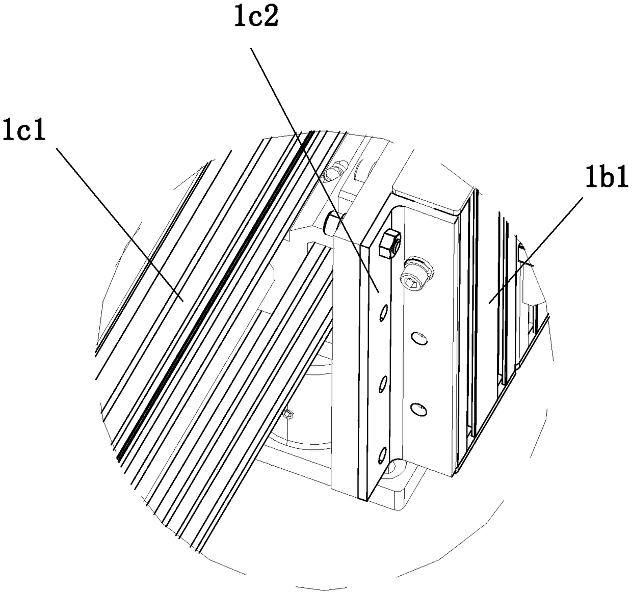
[0026] refer to Figure 1 to Figure 8 The shown conveying device for a thin plate includes a suction device for sucking the thin plate 3, a conveying device and a control device for driving the suction device to move, the suction device and the conveying device are driven and matched, and the suction device and the conveying device are both Electrically connected with the control device, the suction device includes a first suction mechanism 2a and a second suction mechanism 2b arranged at intervals, and the delivery device includes a first drive assembly 1a for driving the suction device to move in the X-axis direction, The second drive assembly 1b used to drive the suction device and the first drive assembly 1a to move in the Z-axis direction and the third drive assembly 1b to drive the suction device, the first dr...


PUM


Abstract

The invention relates to the field of conveying equipment and particularly relates to a thin sheet conveying device. The thin sheet conveying device comprises a sucking device, a conveying device anda control device; the sucking device is matched with the conveying device in a transmission manner; the sucking device and the conveying device are both electrically connected with the control device;the sucking device comprises a first sucking mechanism and a second sucking mechanism which are arranged in a spaced manner; the conveying device comprises a first driving component, a second drivingcomponent and a third driving component, wherein the first driving component is used for driving the sucking device to move in the X-axis direction; the second driving component is used for driving the sucking device and the first driving component to move in the Z-axis direction; the third driving component is used for driving the sucking device, the first driving component and the second driving component to move in the Y-axis direction; the control device comprises a controller and a sensor component; and the sensor component is electrically connected with the controller. The thin sheet conveying device provided by the invention can realize precise feeding and discharging of thin sheets, saves a limiting mechanism and lowers the production cost.

Description

technical field [0001] The invention relates to the field of conveying equipment, in particular to a thin plate conveying device. Background technique [0002] Most of the existing conveying devices for loading and unloading thin plates use conveyor belts. During the conveying process, it is difficult to limit the way the thin plates are placed, and it is impossible to achieve accurate loading. Even if it can be accurately loaded, it must be Setting a limit mechanism on the conveyor belt makes the equipment structure too complicated and increases the cost. [0003] Patent No. CN204198040 is a special conveyor for thin plates, including two left and right conveying units, which are characterized in that: the left and right conveying units are composed of two runners and a plurality of uniformly spaced conveying belts Composition, the two runners are respectively located at the left and right ends of the conveyor belt, the right runner of the left conveying unit is located at...

Claims


Application Information

Patent Timeline
Patent Type & Authority Applications(China)
IPC IPC(8): B65G47/91
CPCB65G47/912B65G47/917B65G2201/022
Inventor 王婷
Owner YUNHEMAN WALKER TOYS CO LTD
Why Eureka
Try Eureka