Automatic loading and unloading platform for drill rod group

A technology for automatic loading and unloading of drill pipes, applied in drill pipes, drill pipes, and earthwork drilling, etc., can solve the problems of low recovery efficiency, poor working conditions, and small working space for thin and ultra-thin coal seam mining, so as to reduce labor intensity. , saving time and improving the efficiency of coal seam mining

Active Publication Date: 2014-01-29
CHONGQING UNIV
View PDF4 Cites 1 Cited by
  • Summary
  • Abstract
  • Description
  • Claims
  • Application Information

AI Technical Summary

Problems solved by technology

According to the division of coal seam thickness in my country, the thickness of 18 ~ 113m belongs to thin coal seam, and the thickness of less than 18m belongs to extremely thin coal seam. The reserves of thin and extremely thin coal seams are large in my country, and the proportion of thin coal seam reserves in state-owned coal mines alone accounts for about 20%. Large, widely distributed, and locally concentrated. With the decreasing reserves of medium-thick coal seams, the mining of thin and extremely thin coal seams is particularly important. Low efficiency and therefore greater reliance on mining equipment and technology
The auger shearer is a coal mining equipment that can mine thin and extremely thin coal seams and improve the recovery rate of coal resources. It can realize unmanned working face mining and improve the working environment of workers. Shearers generally use monorail crane clamping and manual positioning to load and unload drill pipes, which not only has a high labor intensity for workers and difficult positioning of drill pipes, but also greatly limits coal mining efficiency, resulting in slow mining of thin and extremely thin coal seams. The problem of low internal production

Method used


Image

  • Automatic loading and unloading platform for drill rod group
  • Automatic loading and unloading platform for drill rod group
  • Automatic loading and unloading platform for drill rod group

Examples


Embodiment Construction

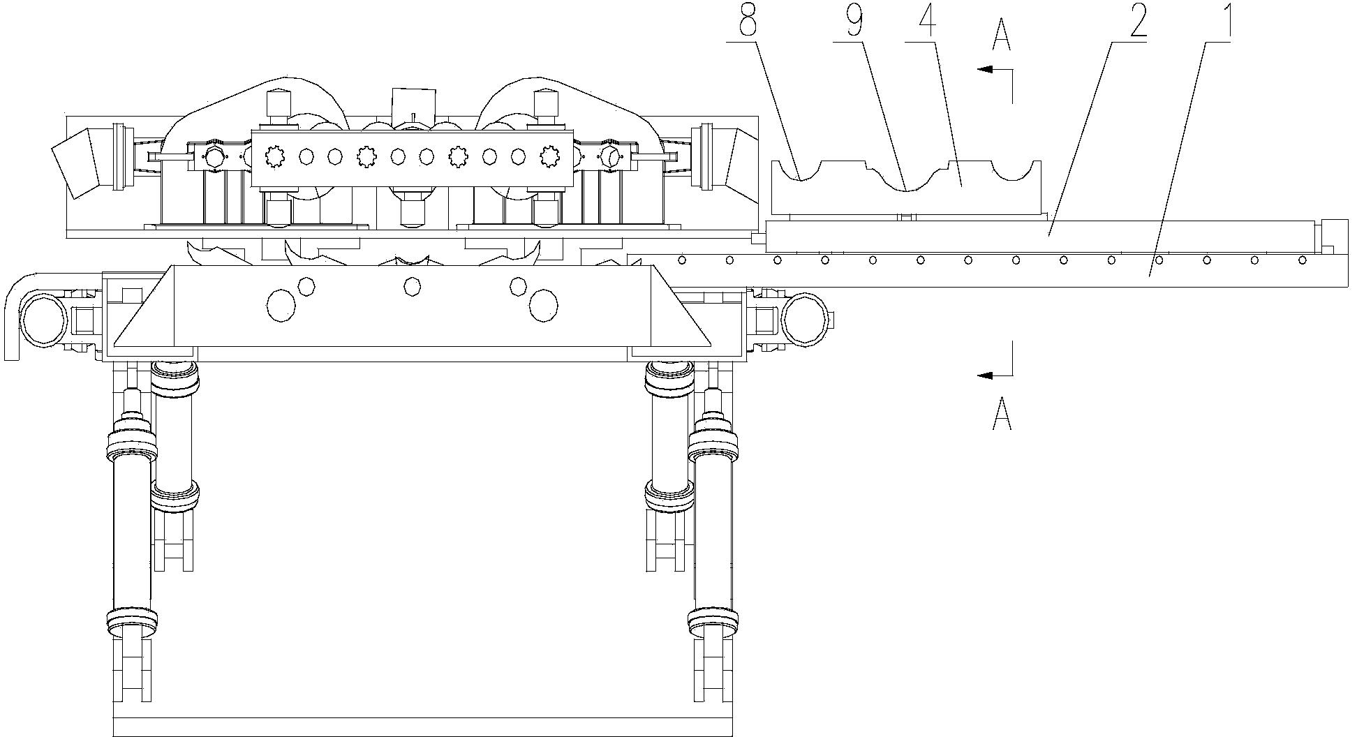
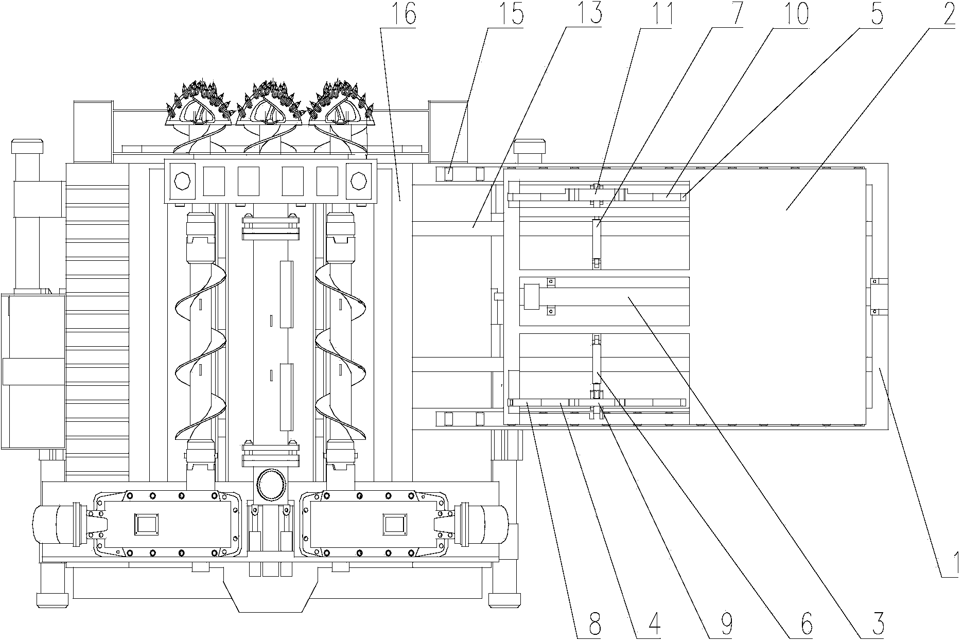
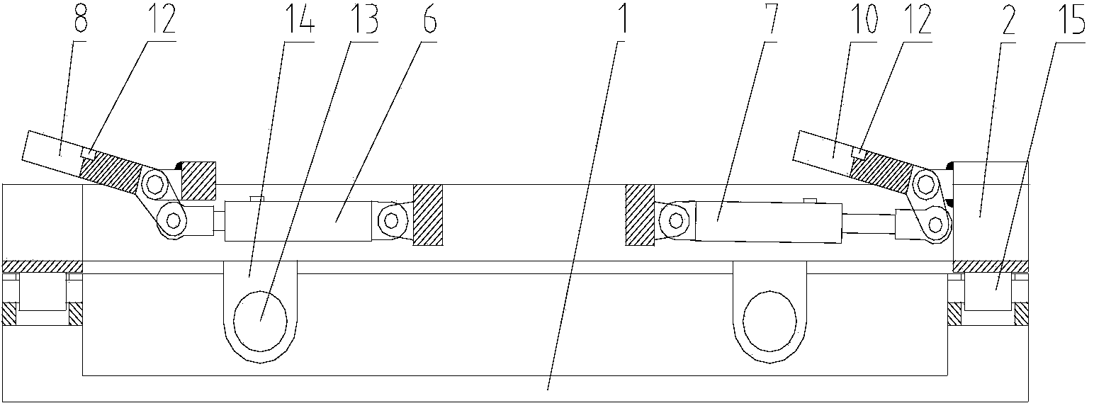
[0020] figure 1 It is a structural schematic diagram of the present invention, figure 2 for figure 1 top view of image 3 for figure 1 A-A sectional view of A-A, as shown in the figure: the automatic loading and unloading platform for drill strings in this embodiment includes a bottom plate 1, a slide table 2, a side-slip driving device 3 and a drill string positioning assembly; the slide table 2 is slidably connected with a single degree of freedom on the bottom plate 1 and driven reciprocatingly by the side sliding drive device 3; the drill string positioning assembly is installed on the slide table 2; Synchronous inclination adjustment and adaptive design of the drill string positioning component structure make the axis of the drill string after positioning and the axis of the main shaft of the auger shearer always on the same plane, and make the axis of the drill string after positioning reach the sliding surface of slide table 2 The vertical distance is equal to the ...


PUM


Abstract

The invention discloses an automatic loading and unloading platform for a drill rod group. The automatic loading and unloading platform comprises a bottom plate, a sliding table, a side sliding driving device and a drill rod group positioning component, the sliding table is slidably connected to the bottom plate by single degree of freedom and is driven by the side sliding driving device to slide in a reciprocating manner, the drill rod group positioning component is mounted on the sliding table, drill rods and air ducts are combined to form the drill rod group which can be conveyed to the space between a spindle of a spiral drill type coal mining machine and a connected drill rod group through the sliding table after the drill rod group is placed and positioned on the automatic loading and unloading platform for the drill rod group, a main engine is controlled to advance, so that the drill rod group can be connected, the sliding table can return to an original position after connection, a next drill rod group is mounted, the drill rod group can be detached by the aid of reverse execution, manual loading and unloading can be replaced, the labor intensity of workers is reduced, the drill rod group can be accurately positioned, the drill rods are successfully loaded and unloaded, time consumption is reduced, and the mining efficiency of coal beds is improved.

Description

technical field [0001] The invention relates to a drilling rod assembly and unloading device for an auger coal shearer, in particular to an automatic loading and unloading platform for a drilling rod. Background technique [0002] my country is a country with large coal production and consumption. With economic growth, the demand for coal is also rising. According to the division of coal seam thickness in my country, the thickness of 18 ~ 113m belongs to thin coal seam, and the thickness of less than 18m belongs to extremely thin coal seam. The reserves of thin and extremely thin coal seams are large in my country, and the proportion of thin coal seam reserves in state-owned coal mines alone accounts for about 20%. Large, widely distributed, and locally concentrated. With the decreasing reserves of medium-thick coal seams, the mining of thin and extremely thin coal seams is particularly important. The efficiency is low, so the dependence on mining equipment and technology is ...

Claims


Application Information

Patent Timeline
Patent Type & Authority Applications(China)
IPC IPC(8): E21B19/18
Inventor 唐倩陈磊毕耀坤于今柏龙陈思宇郭鹏范秋垒刘铁成
Owner CHONGQING UNIV
Why Eureka
Try Eureka