Suction pile with suction device arranged at pile end

A technology of suction device and suction pile, which is applied in the field of suction pile, can solve the problems of complex pile foundation structure, small friction coefficient, high water content, etc., and achieve the effect of increasing the scope of application of the project, increasing the total bearing capacity, and good stability

Active Publication Date: 2018-07-27
ZHEJIANG UNIV OF TECH
View PDF7 Cites 2 Cited by
  • Summary
  • Abstract
  • Description
  • Claims
  • Application Information

AI Technical Summary

Problems solved by technology

[0004] However, when the geological conditions are poor, such as saturated soft clay, its water content is high, its strength is low, and its friction coefficient is small, so the total resistance provided is often small, while the traditional method increases the end area or increases the pile length. The measure of pile foundation bearing capacity has the defects of low efficiency and high cost
At the same time, the traditional method of increasing the contact area at the end to increase the bearing capacity of the pile foundation makes the pile foundation structure more complicated and brings great inconvenience to the construction.

Method used


Image

  • Suction pile with suction device arranged at pile end
  • Suction pile with suction device arranged at pile end

Examples


Embodiment Construction

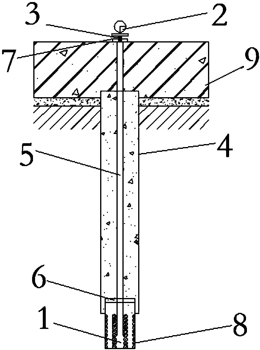
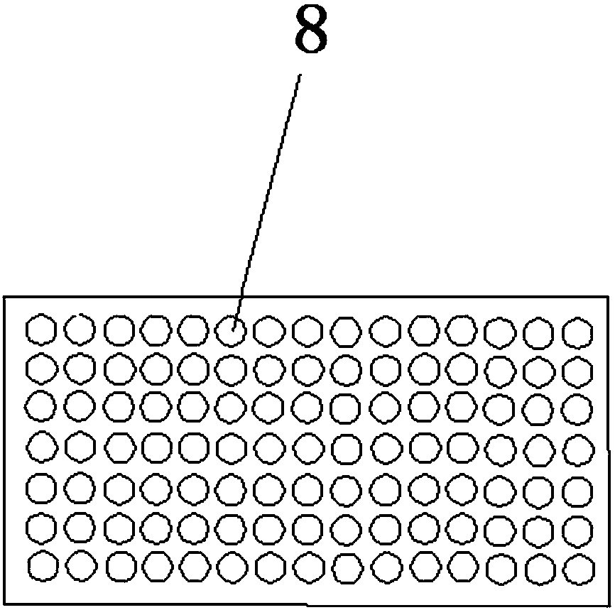
[0020] Referring to the accompanying drawings, a suction pile with a suction device at the pile end includes a columnar pile body 4, the top of the pile body 4 is located in the cap 9 and supports the cap 9 upwards, the bottom of the pile body 4 extends vertically downwards and Embedded in the soil body, and the bottom end of the pile body 4 is connected with a suction device 1 for improving the bearing capacity of the pile end soil (soil body at the end of the pile body 4); the top of the suction device 1 is airtightly embedded in the pile body 4 Inside and fixedly connected with the pile body 4, the bottom end of the suction device 1 extends downwards and exceeds the pile body 4; the suction device 4 is hollow cylindrical, and the top of the suction device 1 is fixedly arranged with 4 The sealing end surface 6 of the airtight partition, and a number of mesh holes 8 communicating with the inner cavity of the suction device 1 are evenly distributed on the side wall of the sucti...


PUM


Abstract

The invention discloses a suction pile with a suction device at the pile end. The suction pile is characterized in that the top end of a pile body is located in a bearing platform and upwards supportsthe bearing platform, the bottom end of the pile body vertically extends downwards and is embedded into a soil body, and the bottom end of the pile body is connected with the suction device; the topend of the suction device is hermetically embedded in the pile body and is fixedly connected with the pile body, and the bottom end of the suction device extends downwards and extends out of the pilebody; the suction device is in a hollow cylinder shape, the top end of the suction device is fixedly provided with a sealing end surface which is hermetically separated from the pile body, and a plurality of screen holes communicating with the inner cavity of the suction device are uniformly distributed on the side wall of the suction device; an air outlet in the top end of an air suction pipe isformed in the top surface of the bearing platform, and an air inlet in the bottom end of the air suction pipe hermetically penetrates through the bearing platform and the pile body and extends into the suction device, and the air inlet in the bottom end of the air suction pipe communicates with the inner cavity of the suction device; and a vacuum valve hermetically penetrates through a sealing cover plate and is arranged on the air outlet in the top end of the air suction pipe, and a pressure measuring meter and the air suction pipe are in hermetical communication.

Description

technical field [0001] The invention relates to a suction pile provided with a suction device at the pile end. Background technique [0002] Pile foundation is an ancient foundation type. Pile technology has experienced thousands of years of development. Whether it is pile foundation materials and pile types, or pile machinery and construction methods, there has been great development, and modern foundation engineering has been formed. system. [0003] In some cases, the use of pile foundations can greatly reduce the amount of foundation work and material consumption on the construction site. The main function of the pile foundation is to balance the upper load or buoyancy on the pile body by the resistance provided by the side wall of the pile body and the soil at the end, so as to provide support for the upper structure or provide anti-lifting force for the building to resist floating. [0004] However, when the geological conditions are poor, such as saturated soft clay...

Claims


Application Information

Patent Timeline
Patent Type & Authority Applications(China)
IPC IPC(8): E02D27/14E02D5/72E02D31/12
CPCE02D5/72E02D27/14E02D31/12E02D2250/0053
Inventor 胡敏云陆雨珂侯暘张勇
Owner ZHEJIANG UNIV OF TECH
Why Eureka
Try Eureka