Pipeline leakage location method based on cross-correlation

A pipeline leakage and location method technology, which is applied in pipeline systems, mechanical equipment, gas/liquid distribution and storage, etc., can solve problems such as difficulty in obtaining prior knowledge, low leak location accuracy, and inaccurate leak location , to achieve accurate pipeline leakage location, low requirements for relevant professional knowledge, simple and easy to achieve

Active Publication Date: 2018-07-27
INST OF ACOUSTICS CHINESE ACAD OF SCI
View PDF6 Cites 24 Cited by
  • Summary
  • Abstract
  • Description
  • Claims
  • Application Information

AI Technical Summary

Problems solved by technology

However, this method has three problems in the actual pipeline leakage location that are difficult to solve: first, when detecting non-metallic pipelines, low water pressure, deep buried pipelines and other working conditions, the accuracy of leak location is not high, and even misjudgment; Second, it is usually necessary to predict the prior knowledge of leakage sound and background noise, and select the non-dispersive frequency band where leakage sound dominates (document [1]: Y.Gao, M.J.Brennan, P.F.Joseph, J.M.Muggleton, O.Hunaidi, A model of the correlation fu...

Method used


Image

  • Pipeline leakage location method based on cross-correlation
  • Pipeline leakage location method based on cross-correlation
  • Pipeline leakage location method based on cross-correlation

Examples


example

[0042] Step 1: When the underground water supply pipeline leaks, select two maintenance wells along the pipeline to be tested, and install a sensor at each end of the pipeline. The sensor type can be an acceleration sensor or a hydrophone. The sensor is connected to the data acquisition instrument, and two sets of time domain signals are collected synchronously.

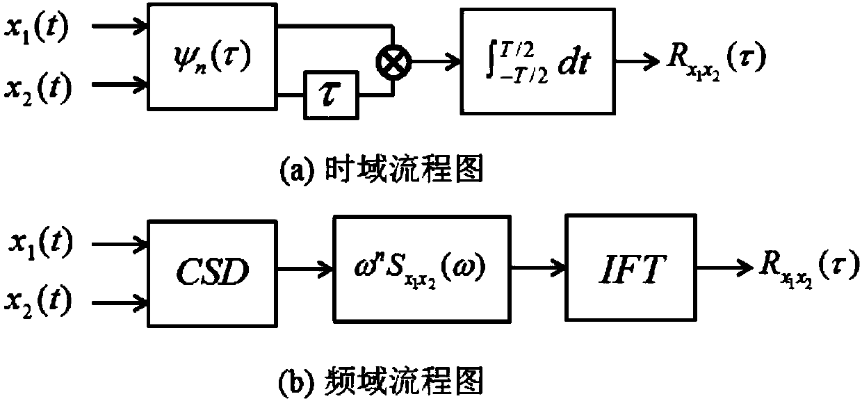
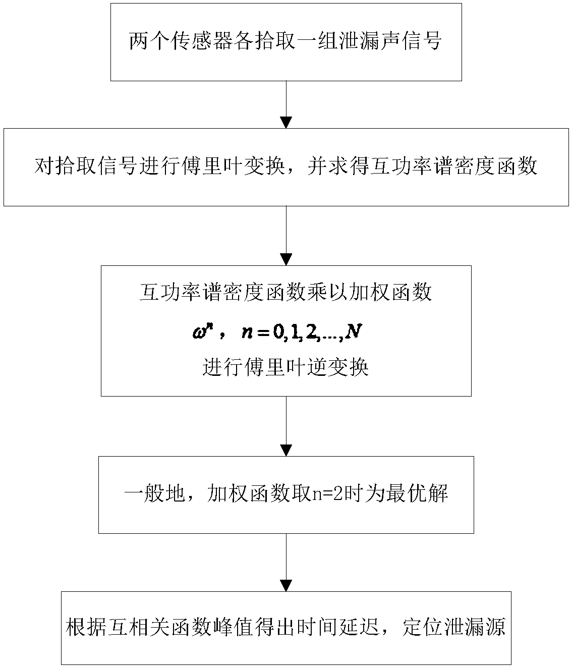
[0043] Step 2: Calculate the time-domain signal x picked up by the two sets of sensors k (t), (k=1,2) cross-power spectral density:

[0044]

[0045] where * denotes complex conjugation. Weight the cross-power spectral density, where the weighting function is set to ω n (n=2), yes Multiplied by the frequency weighting function ω 2 After that, inverse Fourier transform is performed to obtain the cross-correlation function:

[0046]

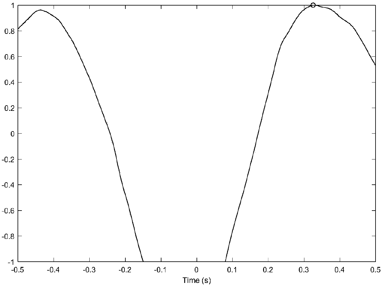
[0047] Step 3: In the experiment, the actual time delay can be calculated by inversion of the positioning formula. The time delay formula can be expressed as:

[0048]

[00...


PUM


Abstract

The invention discloses a pipeline leakage location method based on cross-correlation. The method is implemented on the basis of the following detection device: two sensors are mounted on a to-be-detected pipeline and are acceleration sensors or hydrophones; each sensor is connected with a data acquisition unit which is used for synchronously acquiring leak acoustic signals transmitted in a fluiddue to pipeline leakage. The method comprises the following steps: acquiring leak acoustic time-domain signals picked by the two sensors, and calculating a cross power spectral density function; weighting the cross power spectral density function, performing inverse Fourier transform to obtain a cross-correlation function, acquiring time delay estimation corresponding to a peak value of the cross-correlation function, and accordingly, reversely deriving the distance between a leak point and a first sensor with a location formula. According to the method, filtering processing is not needed forsensor signals, the influence of reflection can be eliminated effectively, and pipeline leakage can be located more accurately under complicated working conditions.

Description

technical field [0001] The invention relates to the field of pipeline transportation, in particular to a method for locating leakage of urban water supply pipelines under complex working conditions, and in particular to a method for locating pipeline leakage based on cross-correlation. Background technique [0002] With the acceleration of urbanization and population increase, the demand for water resources continues to increase. In the planning, construction and operation management of my country's urban water supply pipeline network, there are common problems such as corrosion and aging of underground infrastructure, lack of pipeline information, excessive traffic load and man-made damage, backward monitoring and operation management methods, etc., resulting in frequent pipeline leakage. Pipeline leakage usually accounts for more than 70% of the total water loss, causing direct and indirect energy, economic losses and safety hazards; secondly, the current construction of c...

Claims


Application Information

Patent Timeline
IPC IPC(8): F17D5/06
CPCF17D5/06
Inventor 高艳徐成马一凡崔希望杨军
Owner INST OF ACOUSTICS CHINESE ACAD OF SCI
Why Eureka
Try Eureka