
Working state detection method for bypass diode of photovoltaic module wiring box

A technology of bypass diodes and photovoltaic modules, applied in the direction of diode testing, single semiconductor device testing, etc., can solve the problem of inability to intuitively judge the working status of bypass diodes, the number and specific location of bypass diodes, failure to work normally, and affecting the efficiency of photovoltaic modules and other issues, to achieve the effect of strong test and judgment reliability

Active Publication Date: 2018-07-27
青海黄河上游水电开发有限责任公司西宁太阳能电力分公司 +2
View PDF24 Cites 3 Cited by
  • Summary
  • Abstract
  • Description
  • Claims
  • Application Information

AI Technical Summary

Problems solved by technology

[0005] At present, many modules produced by Chinese module manufacturers have many quality problems and hidden dangers, and a large part of the quality problems of modules come from the design and quality of the junction box itself, whether the bypass diodes in the photovoltaic junction box can work normally Will directly affect the efficiency of photovoltaic modules
[0006] During the process of installing the bypass diode into the junction box, the bypass diode is likely to be damaged in various forms such as thermal shock, mechanical stress, and electrostatic shock. Defective product, making it not work properly on PV modules
[0007] At present, there is no effective and feasible detection method to judge whether the bypass diode has failed before or during installation. In the mass production process, the damaged bypass diode can only be judged or replaced according to the actual use of the power station after the junction box is installed. In the actual operation process, it is impossible to intuitively judge the working status of the bypass diodes and determine the number and specific location of the damaged bypass diodes, which brings challenges to the product quality and reliability of the industrial production of photovoltaic modules.

Method used


Image

  • Working state detection method for bypass diode of photovoltaic module wiring box
  • Working state detection method for bypass diode of photovoltaic module wiring box
  • Working state detection method for bypass diode of photovoltaic module wiring box

Examples


Embodiment Construction

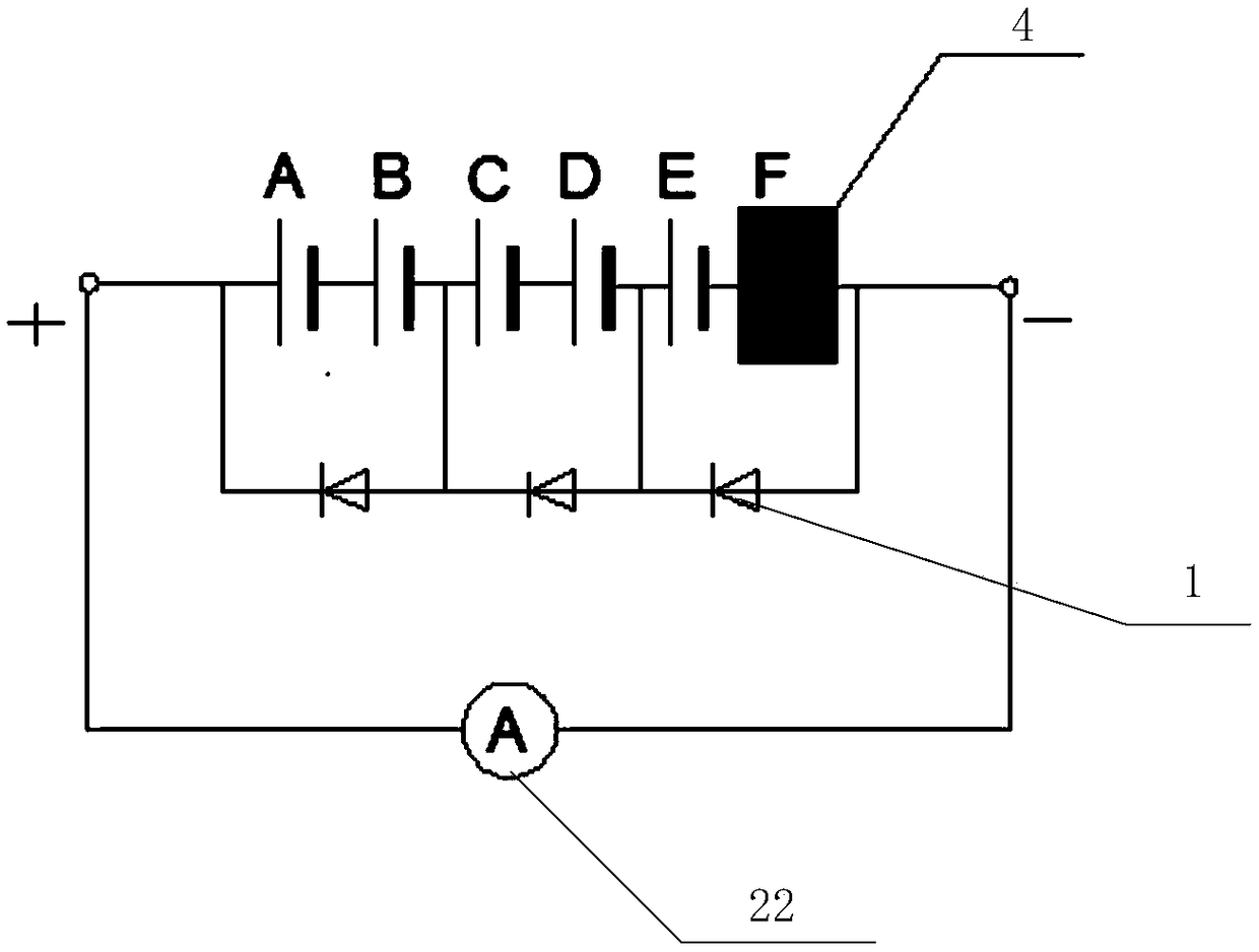
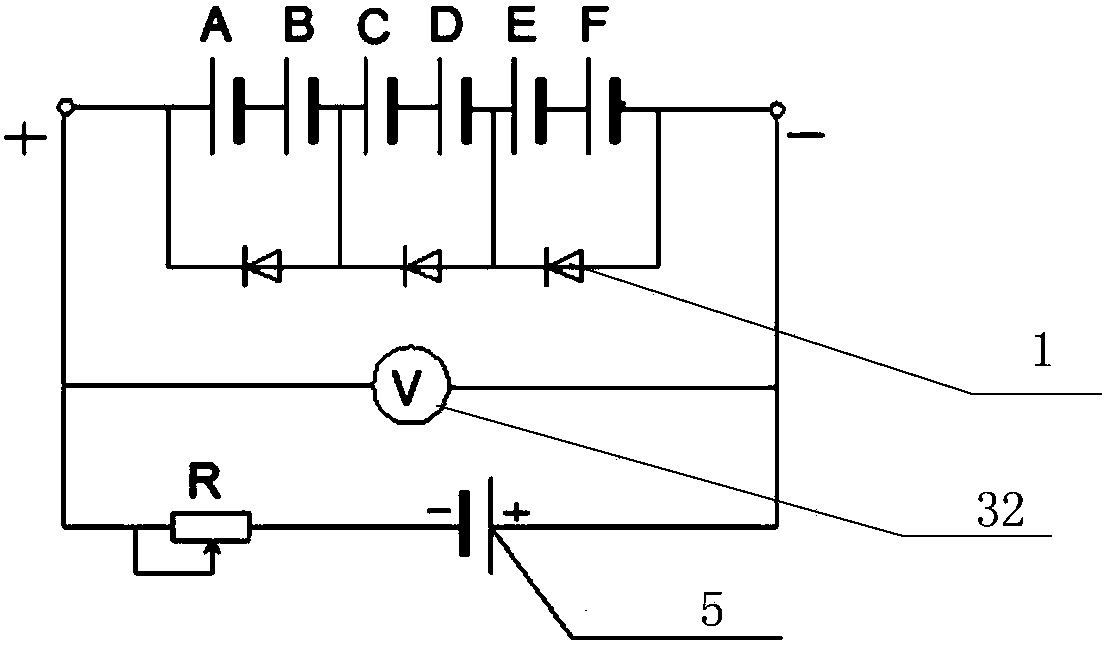
[0034] The method for detecting the working state of the bypass diode of the junction box of the photovoltaic module proposed by the present invention will be further described in detail below in conjunction with the accompanying drawings and specific embodiments. Advantages and features of the present invention will be apparent from the following description and claims. It should be noted that all the drawings are in a very simplified form and use imprecise scales, and are only used to facilitate and clearly assist the purpose of illustrating the embodiments of the present invention.

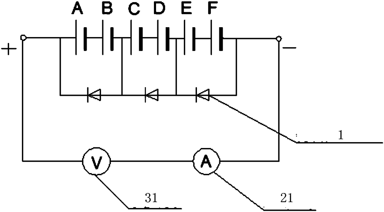
[0035] Please refer to figure 1 ,Such as figure 1 As shown, the embodiment of the present invention provides a method for detecting the working state of the bypass diode of the photovoltaic module junction box, including: detecting the bypass diode of the photovoltaic module junction box to determine whether it is short-circuited; specifically including:

[0036] S11: Connect the first voltme...


PUM


Abstract

The invention discloses a working state detection method for a bypass diode of a photovoltaic module wiring box. The method comprises the steps that voltage U1 and I1 of wiring ports connected to thepositive and negative sides of the normal photovoltaic module wiring box are tested, actual testing values of U1 and I1 are analyzed and compared with voltage output U0 and current output I0 of a normal photovoltaic module, and then whether or not the bypass diode in the photovoltaic module wiring box normally works is judged and the specific number of non-working bypass diodes is judged; a battery piece in parallel connection with the corresponding bypass diode is shielded, and meanwhile if output current I1 at the two ends of the wiring box is remarkably greatly reduced before and after shielding, the open circuit or breakdown exists in the bypass diode in parallel connection with the battery piece at the shielding position can be judged. The working state detection method is simple, effective, high in testing judgment reliability and easy to popularize, and the cost of judging the working state of the diode of the wiring box in the large-batch production process is low.

Description

technical field [0001] The invention relates to the technical field of photovoltaic module detection, in particular to a method for detecting the working state of a bypass diode of a junction box of a photovoltaic module. Background technique [0002] Because of its cleanness, safety, convenience, and high efficiency, solar photovoltaic power generation has become an emerging industry that is widely concerned and focused on development by countries all over the world. Therefore, in-depth research and utilization of solar energy resources is of great significance to alleviate the resource crisis and improve the ecological environment. [0003] According to the "China Photovoltaic Industry Development Roadmap (2016 Edition)", under the background of global warming and the depletion of fossil energy, the development and utilization of renewable energy is increasingly valued by the international community. It is predicted that by 2030, the cumulative installed capacity of photov...

Claims


Application Information

Patent Timeline
Patent Type & Authority Applications(China)
IPC IPC(8): G01R31/26
CPCG01R31/2632
Inventor 王锐左燕刘建达王琪张星孙伟
Owner 青海黄河上游水电开发有限责任公司西宁太阳能电力分公司
Learn More