System for increasing inlet temperature of SCR denitration reactor by utilizing flue gas recirculation

A flue gas recirculation and denitration reactor technology, which is applied in gas treatment, chemical instruments and methods, dispersed particle filtration, etc. The effect of temperature increase, smoke emission reduction and investment saving

Pending Publication Date: 2018-07-31
武汉致衡环境安全工程技术有限公司
View PDF5 Cites 2 Cited by
  • Summary
  • Abstract
  • Description
  • Claims
  • Application Information

AI Technical Summary

Problems solved by technology

Due to the introduction of normal temperature air, the amount of flue gas increases, and the introduction of flue humidification and normal temperature water, the temperature of the flue gas at the outlet of the dust collector is greatly reduced, which cannot meet the SCR denitrification reactor catalytic reduction SCR reaction temperature requirements, such as 150~ 250°C, it is necessary to heat the flue gas to meet the corresponding temperature requirements
The existing flue gas treatment system has problems such as the excessive heat required to reach the SCR denitrification reactor, and the increase in system flue gas emissions.

Method used


Image

  • System for increasing inlet temperature of SCR denitration reactor by utilizing flue gas recirculation
  • System for increasing inlet temperature of SCR denitration reactor by utilizing flue gas recirculation
  • System for increasing inlet temperature of SCR denitration reactor by utilizing flue gas recirculation

Examples


Embodiment 1

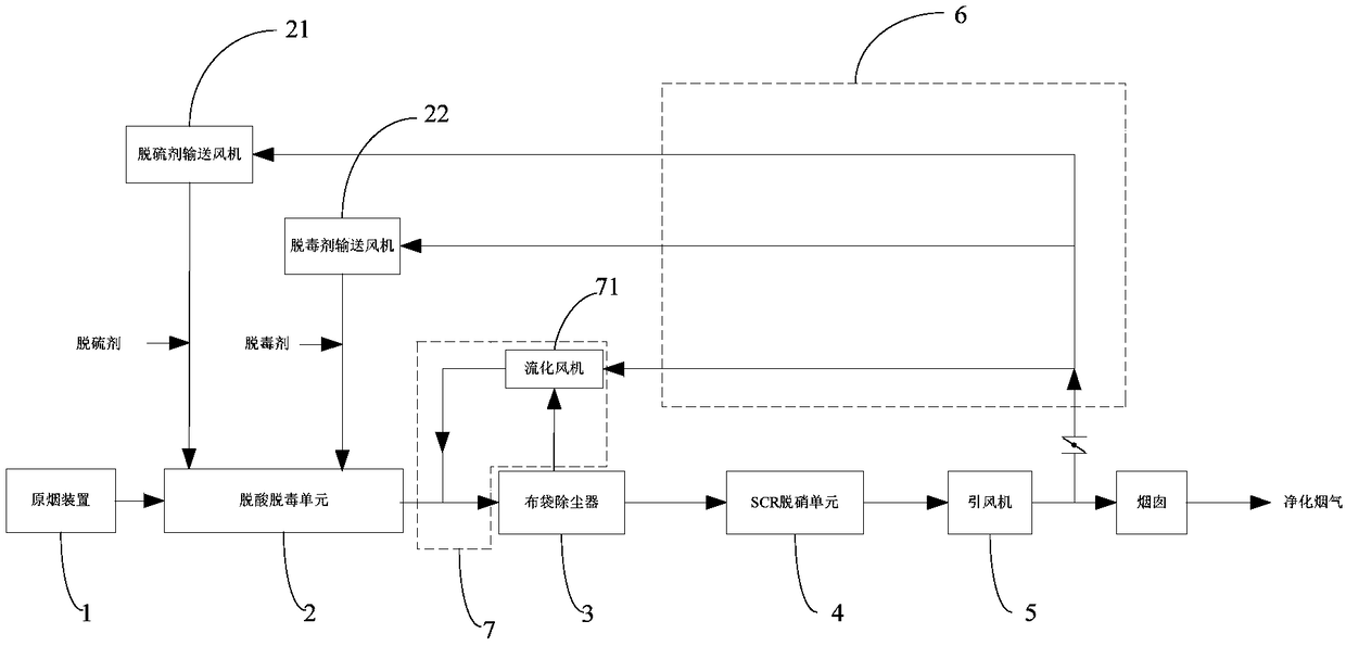
[0026] see figure 1 , the smoke inlet end of the flue gas recirculation pipeline 6 is led from the outlet flue of the bag filter 3; the flue gas deacidification and detoxification unit 2 includes a desulfurizing agent delivery fan 21 and a detoxification agent delivery fan 22; The bag filter 3 is provided with a fly ash circulation pipeline 7, and the fly ash circulation pipeline 7 is configured to allow the dust collected by the bag filter 3 to enter the flue upstream of the bag filter 3 again. The fly ash circulation pipeline 7 is provided with a fluidization fan 71 . The air inlets of the desulfurizing agent delivery fan 21 , the detoxification agent delivery fan 22 and the fluidization fan 71 are all connected to the smoke outlet end of the flue gas recirculation pipeline 6 .

[0027] The smoke inlet end of the flue gas recirculation pipeline 6 in this embodiment is led from the flue between the bag filter 3 and the SCR denitrification unit 4, and the waste heat flue gas ...

Embodiment 2

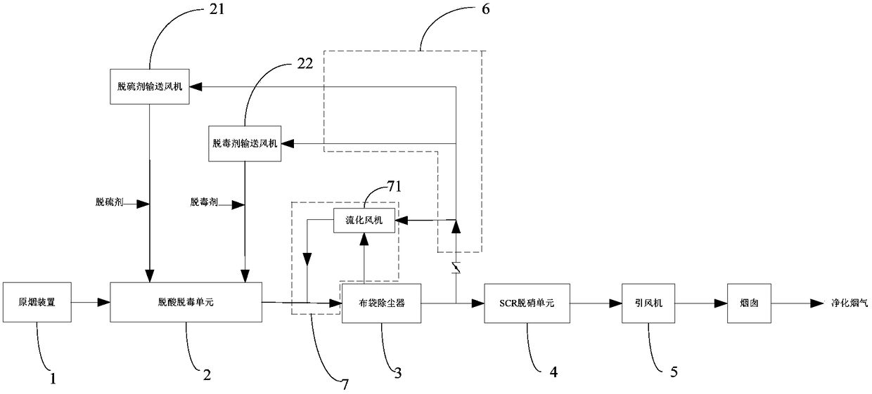
[0029] see figure 2 , the smoke inlet end of the flue gas recirculation pipeline 6 is drawn from the air outlet of the induced draft fan 5; the flue gas deacidification and detoxification unit 2 includes a desulfurizing agent delivery fan 21 and a detoxification agent delivery fan 22; The bag filter 3 is provided with a fly ash circulation pipeline 7, and the fly ash circulation pipeline 7 is configured so that the dust collected by the bag filter 3 enters the flue upstream of the bag filter 3 again. The ash circulation pipeline 7 is provided with a fluidization fan 71; the desulfurization agent delivery fan 21 and the detoxification agent delivery fan 22, and the air inlet of the fluidization fan 71 are all connected to the flue gas recirculation pipeline 6 The smoke outlet is connected.

[0030]The smoke inlet end of the flue gas recirculation pipeline 6 is led from the air outlet of the induced draft fan 5, and the waste heat flue gas at the air outlet of the induced draf...


PUM


Abstract

The invention discloses a system for increasing the inlet temperature of an SCR denitration reactor by utilizing flue gas recirculation. The system comprises an original smoke device, a flue gas deacidifying and detoxifying unit, a bag dust collector, an SCR denitration unit, an induced draft fan and a flue gas recirculating pipeline which are sequentially connected by flues, wherein the flue gasrecirculating pipeline is provided with a smoke inlet end and a smoke outlet end; the smoke inlet end is connected to an outlet flue of the induced draft fan, or is connected to an outlet flue of thebag dust collector; the smoke outlet end is connected with an upstream flue of the bag dust collector. According to the system disclosed by the invention, by arranging the flue gas recirculating pipeline, waste heat flue gas from the outlet flue of the bag dust collector or the outlet flue of the induced draft fan is brought back to the upstream of the bag dust collector and the waste heat flue gas in the system is fully utilized, so that the inlet temperature of the SCR denitration unit is increased, heating energy of input flue gas of the SCR denitration unit is reduced, and operating conditions of the SCR denitration unit are ensured; in addition, the smoke exhausting amount of a chimney is overall reduced, and the whole system achieves the effect of economical and environment-friendlyoperation.

Description

technical field [0001] The invention relates to the field of environmental protection equipment, in particular to a system for increasing the inlet temperature of an SCR denitrification reactor by utilizing flue gas recirculation. Background technique [0002] At present, in the field of environmental protection, flue gas purification generally uses deacidification, detoxification, and dust removal processes in sequence to realize the pre-treatment of the source flue gas. Before the flue gas enters the SCR denitrification reactor, there are many places that need to use wind sources, such as The fly ash collected in the bag filter contains part of the deacidification agent that has not yet fully reacted in the deacidification reactor. In order to reduce the amount of deacidification agent used and improve the use efficiency of the deacidification agent, fly ash recycling is usually adopted. The air intake of the fluidization fan for fly ash circulation can ensure that the fly...

Claims


Application Information

Patent Timeline
Patent Type & Authority Applications(China)
IPC IPC(8): B01D53/75B01D53/86B01D46/02B01D53/50
CPCB01D46/02B01D53/50B01D53/75B01D53/8631B01D2258/0283
Inventor 李先旺高云云王光坤张前进刘良栋
Owner 武汉致衡环境安全工程技术有限公司
Why Eureka
Try Eureka