Milling cutter disc for milling cutter

A technology for milling cutter discs and milling cutters, which is applied to milling cutters, milling machine equipment, clamping, etc., can solve the problems of inconvenient installation and disassembly of milling cutters, low stability performance, and influence on machining accuracy, so as to achieve convenient and fast installation and disassembly, Good stability and good precision

Inactive Publication Date: 2018-07-31
常州苏德工具有限公司
View PDF0 Cites 0 Cited by
  • Summary
  • Abstract
  • Description
  • Claims
  • Application Information

AI Technical Summary

Problems solved by technology

[0004] The purpose of the present invention is to solve the problems in the prior art that the milling cutter is not stable when working on the milling cutter disc, the vibration force is large, the milling cutter is easily damaged, the machining accuracy is easily affected, and the installation and disassembly of the milling cutter is not convenient enough. A Milling Cutter Disc for Milling Cutters

Method used


Image

  • Milling cutter disc for milling cutter
  • Milling cutter disc for milling cutter
  • Milling cutter disc for milling cutter

Examples


Embodiment 1

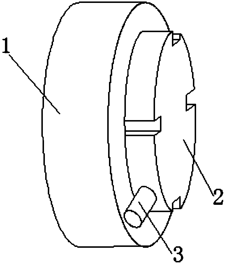
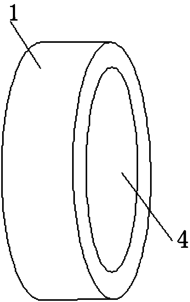
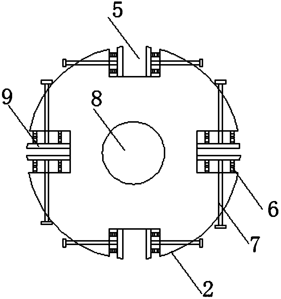
[0021] see Figure 1-4 As shown, a milling cutter disc for a milling cutter includes a fixing plate 1, a mounting plate 2 and a slot 5, one end of the fixing plate 1 is connected with a mounting plate 2, and the mounting plate 2 is connected to the fixing plate 1 through a screw rod 8, and the mounting plate is in operation 2 is installed on one end of the fixed plate 1 through the screw 8 and the screw hole 4, so that the installed plate 2 can be freely disassembled from the side of the fixed plate 1. 2 There are four groups of card slots 5 evenly arranged inside, and push plates 9 are connected to both sides of the card slots 5, and several damping springs 6 are evenly installed on one side of the push plate 9 and the inner side of the card slots 5, to be used during work The milling cutter is clamped inside the draw-in groove 5, and the shock-absorbing spring 6 promotes the tight connection between the push plate 9 and the outer two sides of the milling cutter. The milling ...

Embodiment 2

[0023] Additionally, according to Figure 1-4 As shown, the difference between it and the above-mentioned embodiment is that: one side of the mounting plate 2 is connected with a connecting pipe 3, and the connecting pipe 3 is connected to several perforations 10 through an internal pipe. The liquid flows out from the perforation 10 to reduce the temperature of the milling cutter inside the slot 5 and remove debris outside the milling cutter, which is beneficial to improving the working efficiency of the milling cutter. The middle end of the fixing plate 1 is provided with a screw hole 4, and the mounting plate 2 is movably connected with the fixing plate 1 through the screw rod 8 and the screw hole 4. Maintenance is simple. Both sides of the slot 5 are connected with fastening bolts 7, and one end of the fastening bolts 7 runs through the fixed plate 1 to connect to the push plate 9, the milling cutter is clamped inside the slot 5, and the fastening bolt 7 can be turned to f...


PUM


Abstract

The invention discloses a milling cutter disc for a milling cutter. The milling cutter disc comprises a fixed plate, a mounting plate, a connection pipe, a screw hole, clamping grooves, damping springs, fastening bolts, a screw rod, push plates, perforations and bosses. The milling cutter disc has the beneficial effects that by connecting the interiors of the clamping grooves with the corresponding push plates, a milling cutter to be used in work can be clamped in each clamping groove, the damping springs push the corresponding push plates to tightly connect the push plates with the two sidesof the outer parts of the corresponding milling cutters, the interior of each milling cutter is good in stability, and the clamping grooves can be suitable for the milling cutters with different sizes; in addition, the damping springs in work have the functions of buffering and vibration reduction; when the milling cutters are subjected to vibration during work, the damping springs absorb a part of vibration force; blade positions of the milling cutters during work are difficult to change, and the accuracy of processing a product and the manufactured product are better; in addition, the milling cutters are difficult to damage when being used, the rigidity force applied to the milling cutters is lowered, and the safety performance is better.

Description

technical field [0001] The invention relates to a milling cutter disc, in particular to a milling cutter disc for a milling cutter, belonging to the field of milling cutter installation applications. Background technique [0002] The milling cutter disc is a tool used for milling the plane of the workpiece in the machining process. It is called a milling cutter disc because it is larger than the general milling cutter and has a disc-like shape. The milling cutter is generally equipped with an inlaid carbide blade that does not need to be reground. The milling cutter is installed on the spindle of the milling machine, and the carbide blade is pressed on the cutter with the wedge on the cutter. Then clamp the workpiece to be milled on the machine vise, or press it on the working bed of the milling machine, then start the spindle, and the milling cutter disc will rotate, and the plane can be milled. [0003] But existing milling cutter head still has certain deficiency when us...

Claims


Application Information

Patent Timeline
IPC IPC(8): B23Q3/00B23Q11/10B23C5/00
CPCB23Q3/00B23C5/00B23Q11/10
Inventor 薛成新李锦
Owner 常州苏德工具有限公司
Why Eureka
Try Eureka