
Temperature-controlled heat storage device and temperature-controlled heat storage container

A heat storage device and heat storage technology, which is applied in the direction of heat storage equipment, indirect heat exchangers, heat exchanger types, etc., can solve the problem of low heat conduction rate of phase change materials, and achieve low heat conduction rate, increased contact area, The effect of increasing the contact area

Pending Publication Date: 2018-07-31
深圳市帝洋科技有限公司
View PDF0 Cites 6 Cited by
  • Summary
  • Abstract
  • Description
  • Claims
  • Application Information

AI Technical Summary

Problems solved by technology

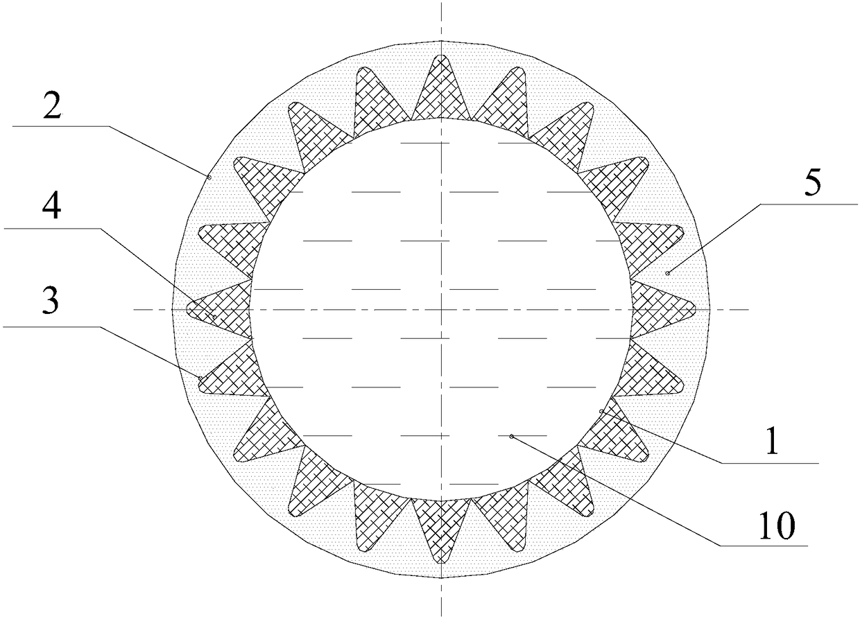
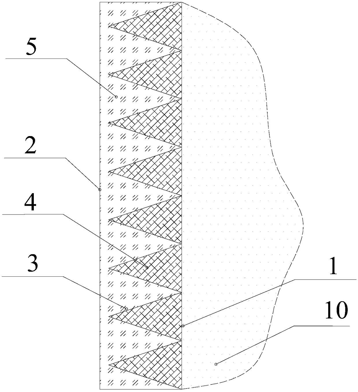
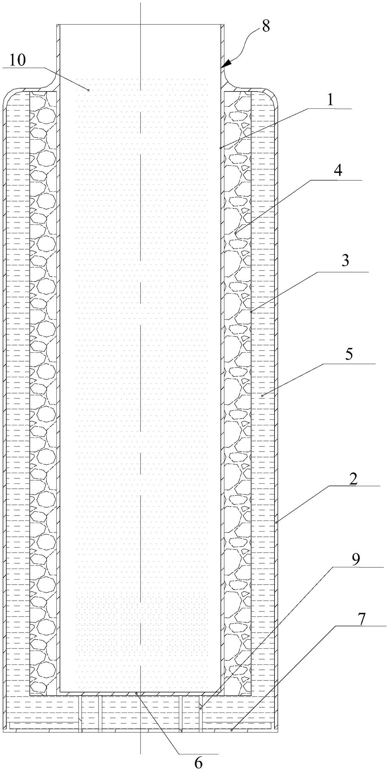
[0004] An object of the present invention is to provide a temperature-controlled thermal storage device, which aims to solve the problem of low thermal conductivity of phase change materials in the prior art

Method used


Image

  • Temperature-controlled heat storage device and temperature-controlled heat storage container
  • Temperature-controlled heat storage device and temperature-controlled heat storage container
  • Temperature-controlled heat storage device and temperature-controlled heat storage container

Examples


Embodiment Construction

[0024] In order to make the object, technical solution and advantages of the present invention clearer, the present invention will be further described in detail below in conjunction with the accompanying drawings and embodiments. It should be understood that the specific embodiments described here are only used to explain the present invention, not to limit the present invention.

[0025] It should be noted that when an element is referred to as being “fixed” or “disposed on” another element, it may be directly on the other element or be indirectly on the other element. When an element is referred to as being "connected to" another element, it can be directly connected to the other element or indirectly connected to the other element.

[0026] It is to be understood that the terms "length", "width", "top", "bottom", "front", "rear", "left", "right", "vertical", "horizontal", "top" , "bottom", "inner", "outer" and other indicated orientations or positional relationships are b...


PUM


Abstract

The invention discloses a temperature-controlled heat storage device. The temperature-controlled heat storage device comprise a first outer wall, a second outer wall, an accommodating plate piece, wherein the first outer wall is in contact with a thermal source; the second outer wall and the first outer wall are arranged at an interval; the accommodating plate piece is arranged on the side surfac,facing the second outer wall, of the first outer wall; a heat-storage interlayer is formed by enclosing between the first outer wall and the second outer wall; an accommodating cavity is formed by enclosing between the accommodating plate piece and the first outer wall; the accommodating plate piece is positioned in the heat-storage interlayer; a heat-transmission substance is arranged in the accommodating cavity; a first phase change material is arranged in the heat-storage interlayer; the first phase change material is in contact with the accommodating plate piece; the heat-transmission substance is arranged in the accommodating cavity to build the surface extruding out of the first outer wall of the accommodating plate piece of the accommodating cavity, a contact area between the firstphase change material and the accommodating plate piece is increased remarkably relative to a contact area between the first phase change material and the first outer wall; the heat-transmission substance passes through the accommodating plate piece after absorbing the heat of the thermal source, and the contact area between the heat-transmission substance and the first phase change material is increased remarkably, and the heat conduction rate of the first phase change material is increased.

Description

technical field [0001] The invention relates to the field of temperature-controlled heat storage, in particular to a temperature-controlled heat storage device and a temperature-controlled heat storage container. Background technique [0002] With the rapid development of the economy, human beings' demand for energy is increasing, and the contradiction of insufficient energy supply is becoming more and more prominent. Therefore, the society's demand for new energy development, improvement of energy utilization efficiency, and energy recovery technology continues to be strong. As a kind of energy, thermal energy plays an important role in human production and life. Heat storage technology is widely used in many fields such as industrial and building heating, air conditioning energy saving, solar heat utilization, waste heat recovery and utilization, among which phase change heat storage technology is an important part of heat storage technology. Heat storage is divided into ...

Claims


Application Information

Patent Timeline
IPC IPC(8): F28D20/02F25D31/00A47G19/22
CPCA47G19/2288F25D31/005F28D20/021Y02E60/14
Inventor 余文斌
Owner 深圳市帝洋科技有限公司
Learn More