Shield segment mechanical simulation test device

A shield segment and simulation test technology, which is applied in the direction of measuring devices, using stable tension/pressure to test material strength, scientific instruments, etc., can solve inaccurate test results, wall damage, and increase the degree of segment damage and other issues to achieve the effect of maintaining flexibility and durability, maintaining flexibility, and ensuring initial non-destructiveness

Pending Publication Date: 2018-07-31
TONGJI UNIV +1
View PDF5 Cites 16 Cited by
  • Summary
  • Abstract
  • Description
  • Claims
  • Application Information

AI Technical Summary

Problems solved by technology

However, the reaction wall loading device takes up a lot of space and is not flexible enough, not only cannot adapt to shield segments with different radii, but also causes wall damage when the load is large; The pressure is generated on the surface of the shield segment by the pull, but this pressure is small and cannot be changed flexibly; the rod plus the central cylinder reaction force device passes the rod through the shield segment, and the tension of the shield segment is generated by the pulling force of the rod. At the same time, self-balancing is achieved at the cylinder, but this kind of device will damage the shield segment, reduce the load-bearing performance of the segment, and lead to inaccurate test results; the vertical loading frame considers the shield segment itself Gravity, but the structure cannot be in a stable equilibrium state, and an impact force will be generated during the loading process, which will increase the damage to the segments and lead to inaccurate test results
In addition, in the test, when the shield segment is subjected to a large load, the structure will undergo large radial deformation and tangential deformation. The existing full-scale test device for shield tunnel cannot maintain the direction of the load under this condition. Stability and accuracy of load magnitude

Method used


Image

  • Shield segment mechanical simulation test device
  • Shield segment mechanical simulation test device
  • Shield segment mechanical simulation test device

Examples


Embodiment Construction

[0038] The present invention will be further described below in conjunction with the embodiments shown in the accompanying drawings.

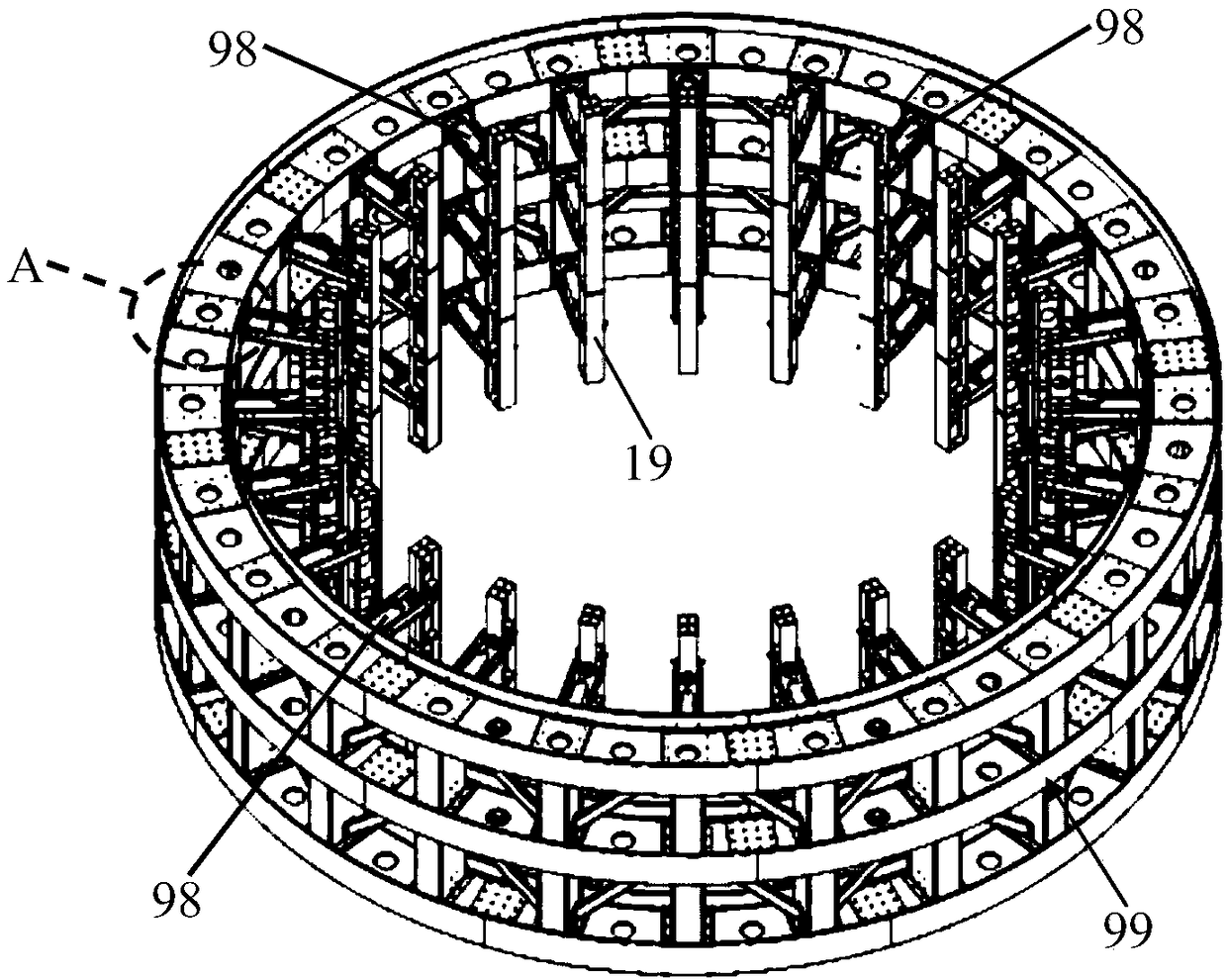
[0039] Such as figure 1 As shown, the present invention firstly provides a mechanical simulation test device for shield tunnel segments, such as figure 1 As shown, the device of the present invention includes a main body reaction force frame 99, ancillary connecting parts, a radial loading mechanism 98, a hydraulic loading device, a sliding type expansion beam 19 and an axial (vertical) loading mechanism. specifically:

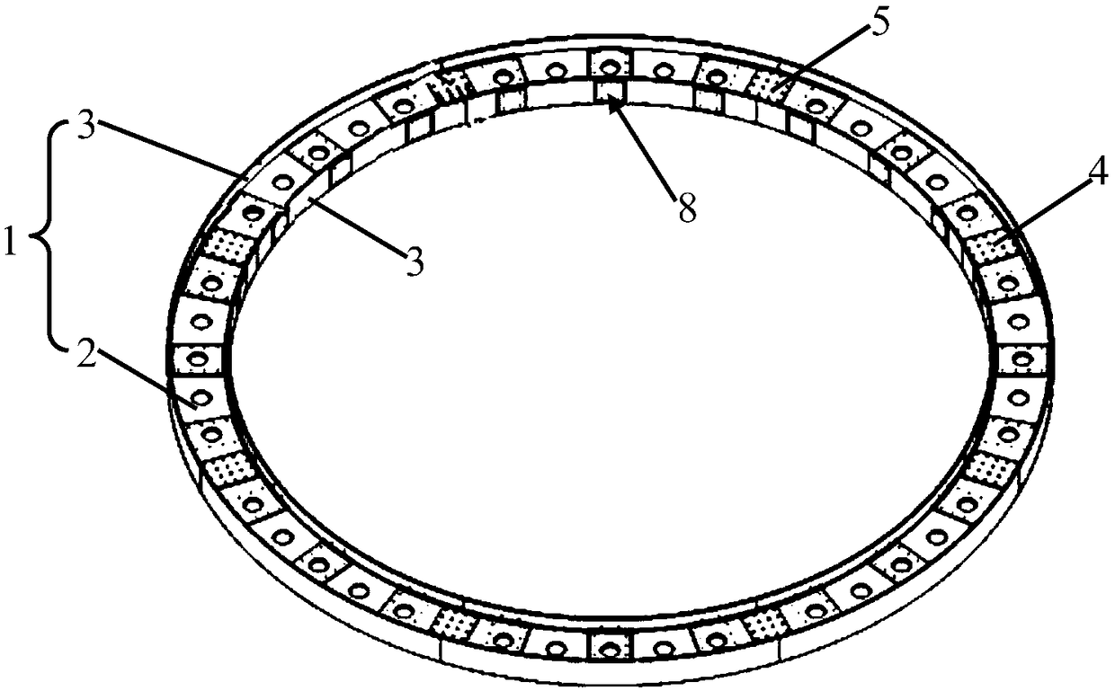
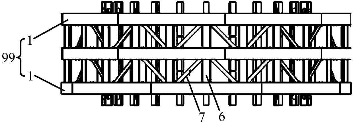
[0040] Such as figure 2 As shown, the main body reaction force frame 99 includes multi-layer reaction force ring units 1 arranged at intervals up and down, as the main body structure bearing the test load and the basis for connecting other components, and the adjacent reaction force ring units 1 pass through columns Connected, a plurality of radial loading mechanisms 98 are evenly distributed on the inner wall of the reacti...


PUM


Abstract

The invention provides a shield segment mechanical simulation test device. The shield segment mechanical simulation test device comprises a main body reaction frame, a radial direction loading mechanism, and an expanding beam; the radial direction loading mechanism comprises an installation end and an extension end; the installation end is adjustably arranged on the internal wall of the main bodyreaction frame, so that angular deflection fine adjustment of the radial direction loading mechanism in a same radial direction plane towards a radial direction can be realized; the expanding beam isdesigned to telescope or extend toward the center of the main body reaction frame with relative to the installation end in an adjustable manner; the expanding beam is arranged along the axis directionof the shield segment, and is detachably arranged on the extension end; the radial direction loading mechanism is used for loading the expanding beam with radial direction loading, and then the radial direction loading is transferred onto the external wall of the shield segment through the expanding beam. According to the shield segment mechanical simulation test device, multifunctional loading and precision guiding are adopted for stimulation of mechanical behaviors of the shield segment, so that sheld segment tunnel full-scale test quality and efficiency are increased.

Description

technical field [0001] The invention belongs to the technical field of tunnel engineering and relates to a mechanical simulation test device for a shield segment. Background technique [0002] With the development of urban rail transit, various safety issues encountered during the construction and service of subway shield tunnels have also received more and more attention. [0003] In view of the load change phenomenon of the subway shield tunnel due to the surrounding construction disturbance encountered in different strata conditions or the change of the bearing performance of the structure itself, it is necessary to accurately simulate the load change process of the shield tunnel, and to comprehensively analyze the segment structure Conduct regular research on the mechanical properties, so as to better maintain the structural safety of the shield tunnel and prolong the service life of the shield tunnel. [0004] For this reason, methods such as numerical simulation, scal...

Claims


Application Information

Patent Timeline
Patent Type & Authority Applications(China)
IPC IPC(8): G01N3/12G01N3/02
CPCG01N3/02G01N3/12
Inventor 金浩周顺华梁东殷剑光周新
Owner TONGJI UNIV
Why Eureka
Try Eureka