Device and method for simulating stress of annular tunnel tire-type lining supporting structure

A technology of supporting structure and lining, which is used in measuring devices, using stable tension/pressure testing materials, instruments, etc., can solve the problem that the real deformation of tunnel lining cannot be measured, it is difficult to have high convincing power, and the measurement location is difficult. and other problems, to achieve the effect of convenient operation, advanced technology and simple installation

Active Publication Date: 2018-07-31
CHINA THREE GORGES UNIV
View PDF7 Cites 8 Cited by
  • Summary
  • Abstract
  • Description
  • Claims
  • Application Information

AI Technical Summary

Problems solved by technology

The measurement methods used above all have certain deficiencies, the measurement position is difficult to ensure accurately, the human measurement error exists objectively, and the real deformation of the tunnel lining in the actual situation is often not measured, and the measured data is difficult to be highly convincing

Method used


Image

  • Device and method for simulating stress of annular tunnel tire-type lining supporting structure
  • Device and method for simulating stress of annular tunnel tire-type lining supporting structure
  • Device and method for simulating stress of annular tunnel tire-type lining supporting structure

Examples


Embodiment 1

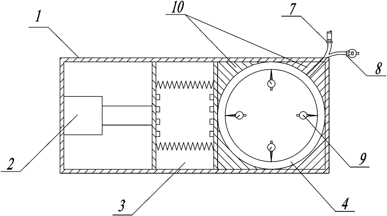
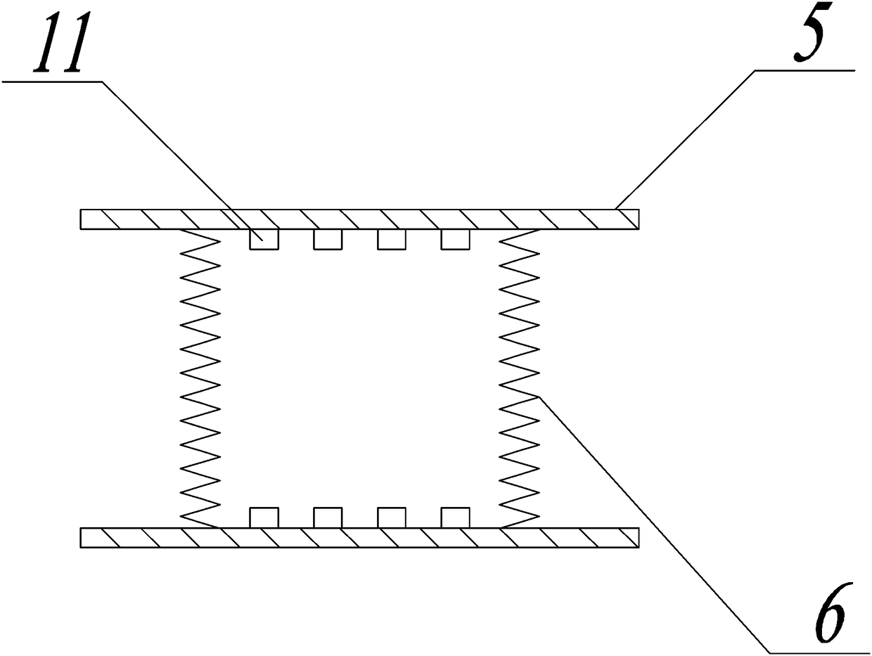
[0044] Such as Figure 1-7 As shown, a device for simulating the stress of the tire-type lining support structure of an annular tunnel includes a rectangular reaction frame 1, a jack 2 is arranged inside the rectangular reaction frame 1, and the base of the jack 2 is connected to the rectangular reaction frame 1. The inner side walls of the force frame 1 are in contact, and the top of the piston rod is in contact with the semicircular contour mold 10 through the force transmission device 3. There are two semicircular contour molds 10, which are symmetrically welded and fixed on the rectangular reaction force frame 1. Inside, the inner wall of the semicircular profile mold 10 is provided with a tire lining 4 in close contact with it. The pressure applied by the surrounding rock of the tunnel is simulated by the jack, and the force is transmitted to the tire lining by means of a force transmission device to simulate the actual force state of the tunnel lining.

[0045] Further,...

Embodiment 2

[0058] A test method for simulating the stress-bearing device of the tire-type lining support structure of an annular tunnel is characterized in that it comprises the following steps:

[0059] Step1: Preparation of the tire lining 4, the material of the carcass is changed from ordinary PVC to silicone rubber after several adjustments;

[0060] Step 2: Connect the automatic pressure relief valve 7 and the digital display air pressure gauge 8 with the carcass of the tire lining 4 as a whole, and fill the airtight carcass with gas;

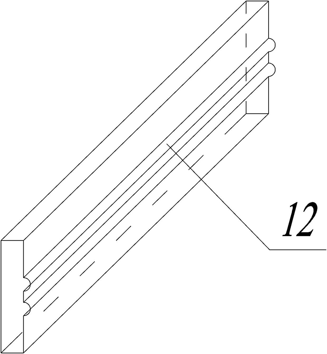
[0061] Step 3: Make a semicircular profile mold 10 as a lining arch ring, using a steel plate, and roll it into two arch rings;

[0062] Step 4: Paste the strain gauge, polish the surface of the lining arch ring and wipe it clean with alcohol, paste the strain gauge, weld the lead wire of the strain gauge to the wire with tin soldering, apply sealing glue, wrap it with insulating tape, and finally strain Sheet resistance measurement to detect the st...


PUM


Abstract

The invention provides a device and method for simulating the stress of an annular tunnel tire-type lining supporting structure. The device comprises a rectangular counterforce frame, a jack is arranged in the rectangular counterforce frame, and a base of the jack is in contact with the inner side wall of the rectangular counterforce frame; the top of a piston rod is in contact with semicircular outline molds through a force transmission device, the two semicircular outline molds are symmetrically and fixedly welded into the rectangular counterforce frame, and tire-type linings are tightly attached to the inner walls of the semicircular outline molds. By adopting the device and method, the actual stress deformation condition of the tunnel linings can be quantitatively simulated, and the theoretical basis is provided for tunnel lining supporting engineering.

Description

technical field [0001] The invention belongs to the technical field of tunnel engineering, and in particular relates to a device and method for simulating the stress of an annular tunnel tire-type lining support structure. Background technique [0002] At present, the methods for measuring the deformation and displacement of the lining include: in actual engineering, after the excavation of the tunnel, use a spiral micrometer to measure the length of several measuring lines on the tunnel section and compare the design length to calculate the deformation; The outline of the tunnel is calibrated successively, and the amount of deformation is calculated by comparing the outline of the tunnel before and after. The above-mentioned measurement methods all have certain deficiencies. The measurement position is difficult to ensure accurately. Human measurement errors exist objectively. It is often impossible to measure the real deformation of the tunnel lining under actual condition...

Claims


Application Information

Patent Timeline
Patent Type & Authority Applications(China)
IPC IPC(8): G01N3/12G01N3/06
CPCG01N3/06G01N3/066G01N3/12G01N2203/0019G01N2203/0075G01N2203/0617G01N2203/0676G01N2203/0682
Inventor 刘杰兰俊燕波高素芳高进张罗送王飞阳菲黎照孙涛蒋旭
Owner CHINA THREE GORGES UNIV
Why Eureka
Try Eureka