A linear vibrating motor

A linear vibration and motor technology, applied in the direction of electric components, electromechanical devices, casings/covers/supports, etc., can solve the problems of poor insulation, inability to achieve quick start and stop, and long motor start and stop time.

Active Publication Date: 2020-01-17
SICHUAN AWA SEIMITSU ELECTRIC CO LTD
View PDF2 Cites 0 Cited by
  • Summary
  • Abstract
  • Description
  • Claims
  • Application Information

AI Technical Summary

Problems solved by technology

However, in actual use, due to the fact that the magnetic induction lines are not restrained and dispersed, the effective utilization rate of the magnetic field is low, resulting in insufficient magnetic field driving force of the energized coil, and the starting and stopping time of the motor is relatively long
In order to solve the above problems, the existing linear motors generally use the upper cover plate on the mass block as a magnetically conductive sheet. However, since there is only a single layer of magnetically conductive material, it cannot provide sufficient driving force for the motor, so that it cannot achieve fast start and stop
Another prior art is to add a magnetically conductive sheet to the coil and the flexible circuit board. However, since the added magnetically conductive sheet is in direct contact with the coil, the coil is easily connected to the cover plate on it, and there is a problem of poor insulation. risk, and when the cover plate is made of non-magnetic material, because there is only a single layer of magnetic material, it cannot provide enough driving force for the motor, so that it cannot be started and stopped quickly, and it is difficult to meet the growing market demand

Method used


Image

  • A linear vibrating motor
  • A linear vibrating motor
  • A linear vibrating motor

Examples


Embodiment 1

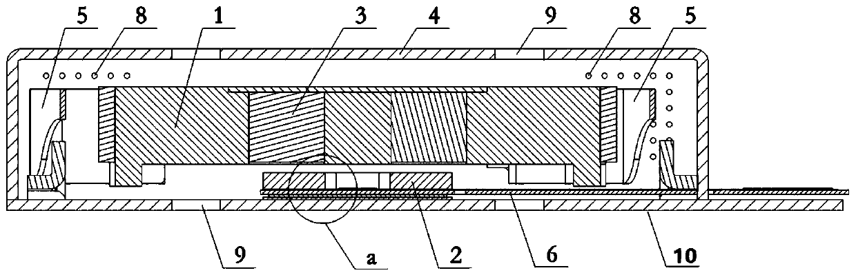
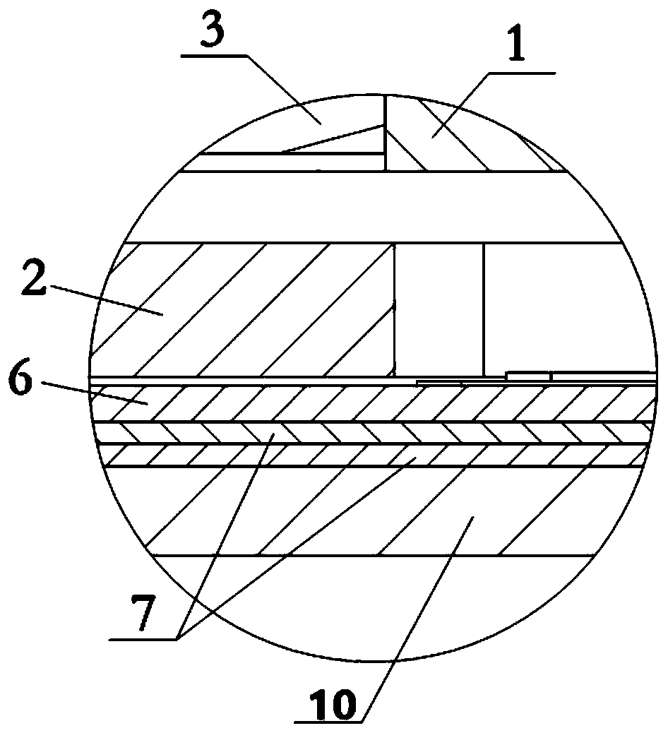
[0029] Such as Figure 1-2 As shown, a linear vibrating motor includes a casing 4 provided with an accommodation space, a vibrating assembly and a stator assembly. The casing 4 can be made of micro-magnetic material or SUS430 stainless steel, wherein the vibrating assembly and the peripheral surface of the stator assembly face each other. The two ends of the vibrating assembly are respectively elastically connected to the inner wall of the housing 4, and the stator assembly is fixedly connected to the inner wall of the housing space; a magnetically conductive sheet is also arranged between the stator assembly and the inner wall of the housing 4 7. The magnetic conductive sheet 7 can be made of ferrite material, such as SUS430 stainless steel, the thickness of the magnetic conductive sheet 7 can be 0.05mm-0.15mm, and the magnetic conductive sheet 7 can be installed by welding or glue bonding . The vibration assembly includes a mass block 1, a magnet 3 and two elastic elements ...

Embodiment 2

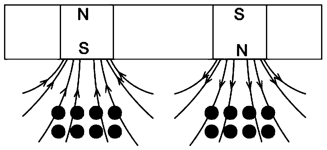
[0031] A linear vibration motor as described in Embodiment 1 may have multiple pieces of magnetically permeable sheets, and the multiple pieces of magnetically conductive sheets may be superimposed by welding. Preferably, two magnetically conductive sheets 7 can be stacked on the side of the flexible circuit board 6 facing away from the vibration component, and the two magnetically conductive sheets 7 can be stacked together by welding. The thickness of each magnetic conductive sheet 7 may be 0.03mm-0.1mm. Compared with Example 1, this Example 2 increases the number of magnetically conductive sheets, thereby enhancing the guiding effect on the magnetic induction lines, making the magnetic induction lines more concentrated, and further increasing the driving force when starting and the damping when stopping force. The magnetically permeable sheet 7 can also have one or more notches so as to avoid the wire ends entering and exiting the coil 2 .

Embodiment 3

[0033] A kind of linear vibrating motor as described in embodiment 1, 2, the bottom wall (that is cover plate 10) adjacent to the stator of its housing 4 is made by magnetically permeable material, such as micro magnetically permeable material, makes this cover plate 10 can also play the role of a magnetically conductive sheet. Compared with Embodiments 1 and 2, since the cover plate 10 of Embodiment 3 also acts as a magnetically conductive sheet, the guiding effect on the magnetic induction lines is further enhanced, and the magnetic induction lines are more concentrated, thereby increasing the Driving force at start and damping force at stop.


PUM


Abstract

The invention discloses a linear vibration motor, which comprises a housing with an accommodating space, a vibration assembly and a stator assembly, wherein the vibration assembly and the stator assembly are oppositely arranged in the accommodating space of the housing; the vibration assembly comprises a mass block, a magnet and two elastic supporting members, the magnet is arranged in the mass block, two ends of the mass block are respectively provided with small bosses which are arranged in a diagonal manner, the two elastic supporting members are respectively arranged at two ends of the mass block, one end of each elastic supporting member is fixedly connected with the mass block and one small boss, the other end is fixedly connected with the inner side wall of the housing, and the upper edge of each elastic supporting member is flush with the top surface of the corresponding small boss. The motor can accurately position a magnetic conductive sheet and can prolong the service life of the elastic supporting members.

Description

technical field [0001] The invention belongs to the field of miniature vibration motors, in particular to a linear vibration motor. Background technique [0002] At present, mobile consumer electronics products on the market generally use vibration motors as system feedback components, such as incoming call prompts for mobile phones, vibration feedback for game consoles, and so on. Existing vibration motors on the market mainly include cylindrical iron core motors, coreless motors and linear motors. Cylindrical iron core motors and coreless motors not only have complex structures, large thickness, and many manufacturing processes, but also have high motor noise and poor control accuracy, so they are rarely used. However, linear motors vibrate smoothly and are widely used in consumer electronics. For the application of horizontal linear vibration motors on the market, the vibrating block and the elastic elements at both ends of the vibrating block are generally arranged in ...

Claims


Application Information

Patent Timeline
Patent Type & Authority Patents(China)
IPC IPC(8): H02K33/02H02K5/20
CPCH02K5/20H02K33/00H02K33/02
Inventor 不公告发明人
Owner SICHUAN AWA SEIMITSU ELECTRIC CO LTD
Why Eureka
Try Eureka