A fluoroscopy-based technique to measure intraoperative cup anteversion

A fluoroscopy and anteversion technology, applied in the field of total hip arthroplasty, which can solve the problems of complex evaluation and difficult realization.

Active Publication Date: 2018-07-31
F 贝特纳
View PDF6 Cites 4 Cited by
  • Summary
  • Abstract
  • Description
  • Claims
  • Application Information

AI Technical Summary

Problems solved by technology

However, the assessment of the CV (forward lean) angle proved to be more complicated
Image-based techniques relying on stan

Method used


Image

  • A fluoroscopy-based technique to measure intraoperative cup anteversion
  • A fluoroscopy-based technique to measure intraoperative cup anteversion
  • A fluoroscopy-based technique to measure intraoperative cup anteversion

Examples


Embodiment Construction

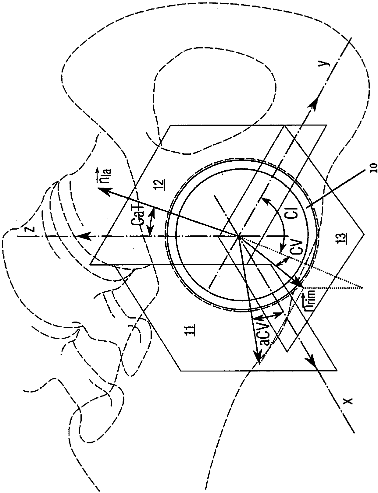
[0033] Such as figure 1 As shown, when describing the position (orientation) of the acetabular cup, CV and CI refer to anteversion and inclination, respectively, as defined by Murray's radiography. exist figure 1 middle, is a vector normal to the equatorial plane of the acetabular cup 10 and is defined by the inclination CI and the anteversion CV. aCV is on section 11 The angle between the projection of and the coronal plane 13. is a vector orthogonal to the plane of the image amplifier of the C-arm. CaT is the tilt angle that needs to be applied to the C-arm in order for the plane of the image amplifier to be perpendicular to the equatorial plane of the cup. which corresponds to and the angle between the z-axis. The sagittal plane is shown as 12.

[0034] CV is thus defined as the angle between a vector perpendicular to the equatorial plane of the cup and the coronal plane 13 . CI is thus defined as the angle between the sagittal plane 12 and the projection on th...


PUM


Abstract

Direct anterior approach (DAA) with the patient lying supine has facilitated the use of intraoperative fluoroscopy and allows for standardized positioning of the patient. The method disclosed herein uses intraoperative fluoroscopy to measure acetabular component anteversion and more particularly, a method for measuring/calculating intraoperative cup (acetabular component) anteversion is provided based on the measured acetabular component abduction angle and a c-arm tilt angle (CaT).

Description

[0001] Cross References to Related Applications [0002] This application claims priority to US Patent Application No. 62 / 201,417, filed August 5, 2015, the entire contents of which are incorporated herein by reference. technical field [0003] The present invention relates to total hip arthroplasty (THA) and more specifically to a direct anterior approach (DAA) in which the patient is in the supine position and for measuring / calculating the intraoperative cup (pseudoacetabular body) anteversion method based on measured acetabular component abduction angle and c-arm tilt angle (CaT). Background technique [0004] Total hip arthroplasty (THA), also known as hip replacement surgery with an artificial prosthesis (total hip arthroplasty), is a reconstructive surgery in which damaged bone and cartilage are removed and replaced with prosthetic components. Total hip replacement is the usual treatment for people with advanced degenerative hip disease; however, chronic pain and impa...

Claims


Application Information

Patent Timeline
IPC IPC(8): A61B5/107A61B6/12A61B17/56A61B34/10A61B34/20A61F2/34A61F2/46
CPCA61B6/12A61F2/34A61B5/107A61B34/20A61B2090/376A61B34/32A61B6/4441A61B6/4482A61B6/505A61B6/5217A61B5/1077A61B5/4528A61F2002/4658A61F2002/4668A61F2/4657A61B6/545A61B34/10G16H50/30A61B2034/2065
Inventor F·贝特纳M·津格
Owner F 贝特纳
Why Eureka
Try Eureka