Actuator device

An actuator device and actuator technology, which are applied in the directions of fluid pressure actuation devices, forging/pressing/hammer devices, punching machines, etc., can solve the problem that the ejector device is not suitable for supporting the formed parts, and achieve a small cost. Effect

Active Publication Date: 2018-07-31
HATEBUR UMFORMMASCHEN
View PDF6 Cites 5 Cited by
  • Summary
  • Abstract
  • Description
  • Claims
  • Application Information

AI Technical Summary

Problems solved by technology

[0004] This known ejector device is not suitable for supporting the molded part in the molding tool during the forming process or for braking the process-dependent displacement of the molded part during the forming process

Method used


Image

  • Actuator device
  • Actuator device
  • Actuator device

Examples


Embodiment Construction

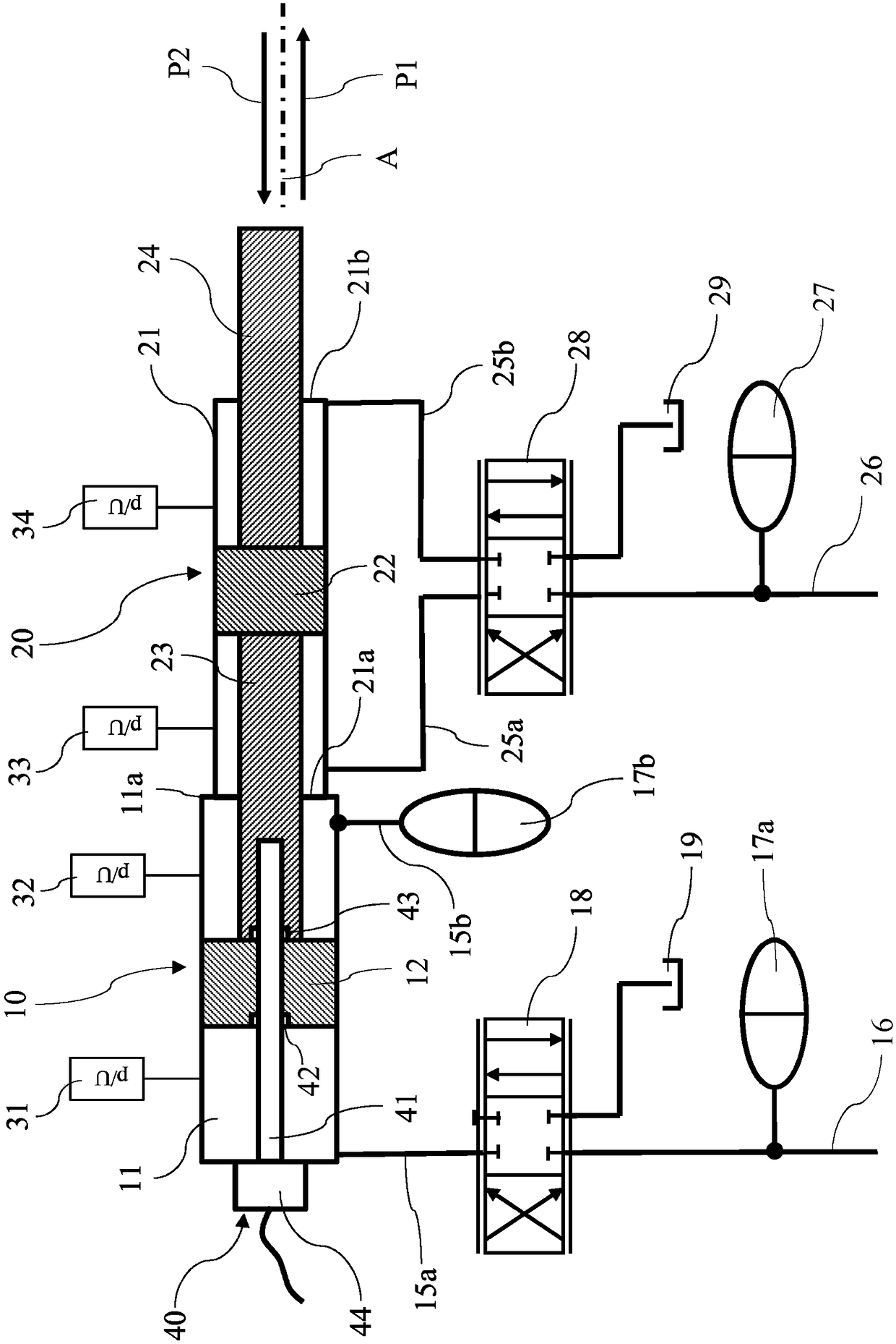
[0030] The actuator device according to the invention is in Figure 1-3 The embodiment presented in the most essential part for its function comprises a first drive unit 10 and a second drive unit 20 . The first drive unit 10 comprises an exemplary cylindrical piston chamber 11 having a linearly displaceable first piston 12 mounted therein. The second drive unit 20 comprises an exemplary cylindrical piston chamber 21 having a second piston 22 mounted linearly displaceably therein. The two piston chambers 11 and 21 are arranged flush next to each other with respect to the axis of movement A and are immovably connected to each other.

[0031] The first piston 11 is connected via two lines 15a and 15b to a first hydraulic mechanism comprising a hydraulic source symbolized only by line 16, two hydraulic accumulators 17a and 17b, for continuous operation Design the first 4-way servo valve 18 and sump 19. As explained further below, only three of the four paths of the servo valve...


PUM


Abstract

The invention relates to an actuator device comprising two drive units (10, 20) for an actuator output drive (24). The first drive unit (10) has a first piston chamber (11), a first piston (12) whichcan be moved in the piston chamber, and first hydraulic means (16, 17a, 17b, 18, 19) for displacing the piston (12). The second drive unit (20) has a second piston chamber (21), a second piston (22) which can be moved in the piston chamber, and second hydraulic or pneumatic means (26, 27, 28, 29) for displacing the piston (22). The second piston (22) is fixedly connected to the actuator output drive (24) and can be coupled to the first piston (12) with respect to thrust such that the second piston (22) can be displaced by the first piston (12) in a direction of extension (PI). The first driveunit (10) is designed for a greater thrust force than the second drive unit (20), whereas the second drive unit (20) is designed for a greater stroke speed than the first drive unit (10).

Description

technical field [0001] The invention relates to an actuator arrangement for the linear movement of the actuator output along the movement axis according to the preamble of independent claim 1 . The invention also relates to the use of said actuator device. Background technique [0002] During the forming process of shaped objects in a forming device, it is often necessary on the one hand to counteract movement during the forming process or also to brake the process-dependent advance of the shaped object in a controlled manner and, on the other hand, to move the formed The item is ejected from the forming die. In this case, comparatively high support or ejection forces are sometimes required. On the other hand, at least the ejection of the shaped objects will take place at a high speed in order to ensure a high machine rhythm of the shaping device. [0003] WO 2010 / 118799 A1 describes an ejector device for ejecting a molded part from a mold of a molding device. The ejecti...

Claims


Application Information

Patent Timeline
Patent Type & Authority Applications(China)
IPC IPC(8): B21D24/14F15B11/036B21D45/02B21J13/14
CPCB21D24/14B21D45/02B21J5/02B21J13/14B30B1/32B30B1/323B30B15/161B30B15/163B30B15/165F15B11/022F15B11/0365F15B15/1409F15B2211/20576F15B2211/212F15B2211/625F15B2211/6336F15B2211/7056F15B2211/775
Inventor 米哈伊·乌尔坎贝恩哈尔·泽瓦斯
Owner HATEBUR UMFORMMASCHEN
Why Eureka
Try Eureka