
Yarn tensioning system and method for keeping a yarn which is taken from a yarn storage system to a yarn take-off system of a weaving machine under tension

A tensioning system, yarn output technology, applied in looms, flannel looms, transportation and packaging, etc., can solve the problems of cumbersome, time-consuming and labor-intensive

Active Publication Date: 2018-07-31
N V MICHEL VAN DE WIELE
View PDF9 Cites 6 Cited by
  • Summary
  • Abstract
  • Description
  • Claims
  • Application Information

AI Technical Summary

Problems solved by technology

[0011] However, the problem with this known yarn tensioning system is that, when the properties of the warp threads (thickness, flexibility, etc.) force on warp
This is a tedious, time-consuming and labor-intensive process as it has to be done for each individual warp thread from the bobbin to the weaving area

Method used


Image

  • Yarn tensioning system and method for keeping a yarn which is taken from a yarn storage system to a yarn take-off system of a weaving machine under tension
  • Yarn tensioning system and method for keeping a yarn which is taken from a yarn storage system to a yarn take-off system of a weaving machine under tension
  • Yarn tensioning system and method for keeping a yarn which is taken from a yarn storage system to a yarn take-off system of a weaving machine under tension

Examples


Embodiment Construction

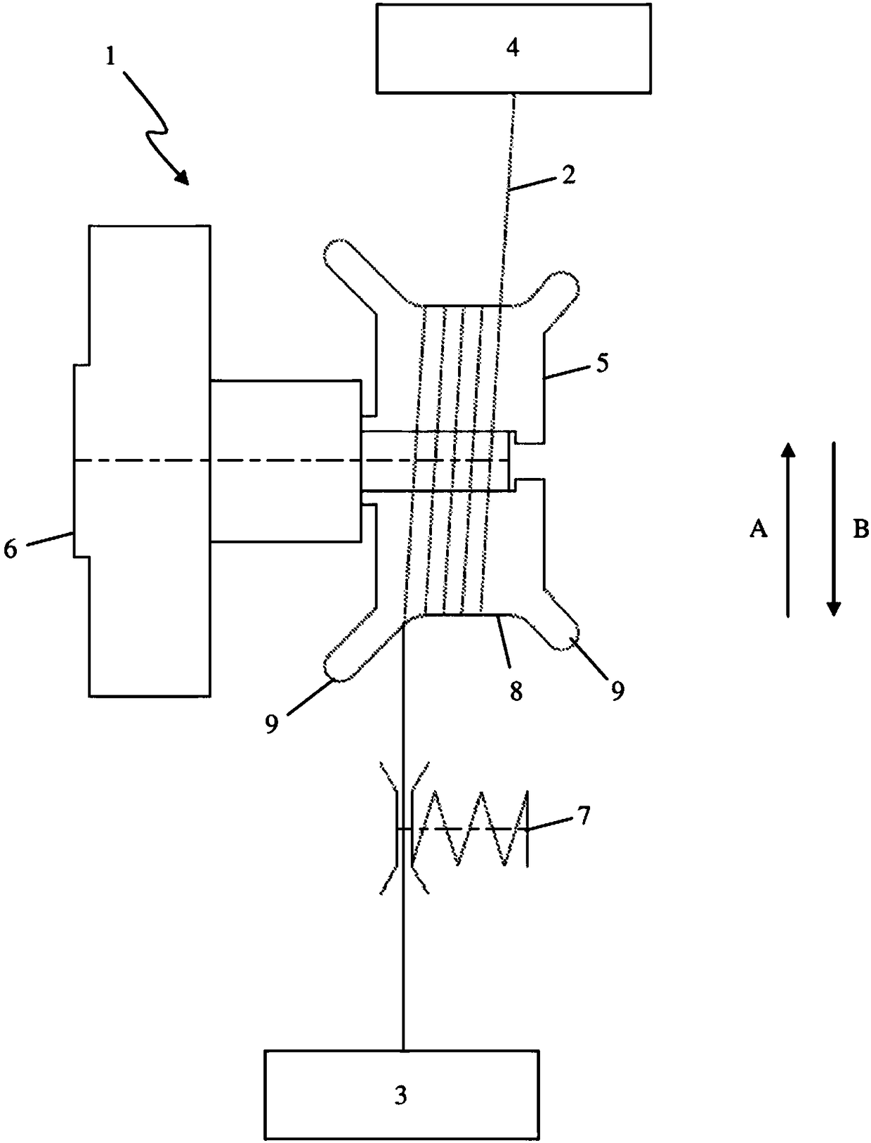
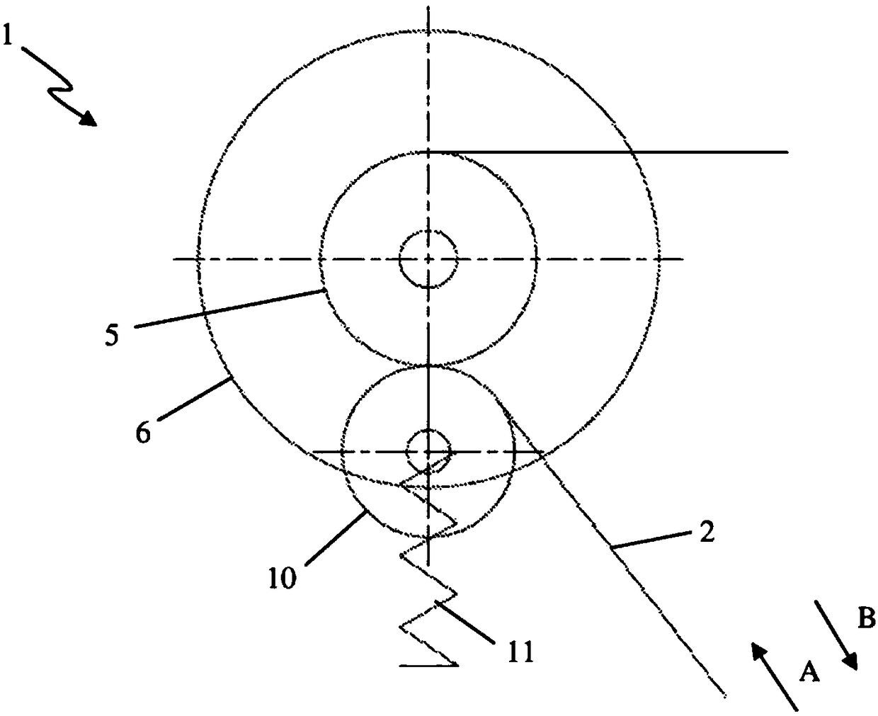
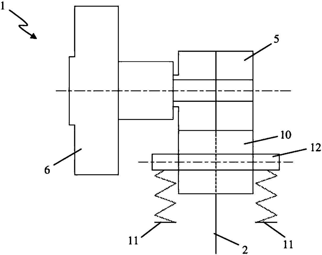
[0060] These figures show some examples of yarn tensioning systems (1) according to the invention.

[0061] Each of these yarn tensioning systems (1) comprises, for each yarn (2) to be tensioned, a rotatably arranged braking roller (5) and a means for supplying the braking roller (5) torque motor (6).

[0062] exist figure 1 In the first embodiment shown, the yarn (2) is withdrawn from the yarn storage system (3) to the yarn delivery system (4) of the loom in a first direction (A), or in a direction (A) A) On the opposite second direction (B) between the braking roller (5) and the yarn output system (4), the yarn (2) is wound several times on the braking roller (5) to limit the yarn (2) Sliding relative to the brake roller (5).

[0063] In order to further limit the sliding of the yarn (2) relative to the braking roller (5), the yarn tensioning system (1) also includes a braking device (7), which is arranged between the yarn storage system (3) and the braking roller (5). b...


PUM


Abstract

The present invention relates to a yarn tensioning system (1) for keeping at least one yarn (2) which is taken from a yarn storage system (3) to a yarn take-off system (4) of a weaving machine under tension, comprising a brake roller (5) around which the yarn (2) is at least partially wound and a motor (6) for supplying a torque to the brake roller (5), which is actuable in generator operation tokeep the yarn (2) under tension between the brake roller (5) and the yarn take-off system (4). In addition, the present invention relates to a weaving machine comprising such a yarn tensioning system(1) and a method for keeping at least one yarn (2) under tension which is taken from a yarn storage system to a yarn take-off system.

Description

technical field [0001] The invention relates to a yarn tensioning system for maintaining under tension at least one yarn withdrawn in a first direction from a yarn storage system to a yarn delivery system of a weaving machine, comprising a brake roller, The braking roller is rotatably arranged in the yarn tensioning system and the yarn is at least partially wound around the braking roller so as to maintain the yarn under tension between the braking roller and the yarn output system . Furthermore, the invention relates to a weaving machine comprising such a yarn tensioning system. [0002] Furthermore, the invention relates to a method for holding under tension at least one yarn withdrawn from a yarn storage system to a yarn delivery system of a weaving machine in a first direction. Background technique [0003] A yarn tensioning system and method for holding under tension a yarn withdrawn from a yarn storage system to a yarn output system in a loom is used in various looms...

Claims


Application Information

Patent Timeline
IPC IPC(8): B65H59/18D03D39/02D03D49/16B65H57/12B65H51/20
CPCB65H59/18B65H57/12B65H51/20D03D39/02D03D49/16B65H2701/31B65H59/06
Inventor C.博杜因G.德布夫H.德斯梅特K.布鲁伊诺格K.维瑟尔
Owner N V MICHEL VAN DE WIELE
Learn More