
A Method for Optimizing the Shear of Steel Plate Head

An optimized, steel plate technology, applied in the direction of shearing devices, shearing machine accessories, metal processing equipment, etc., can solve the problems of large data errors, inability to describe the shape of the slab head, and many external interference factors. Achieve the effect of improving precision, improving shearing efficiency and reducing labor intensity

Active Publication Date: 2017-02-22
BAOSHAN IRON & STEEL CO LTD +1
View PDF8 Cites 0 Cited by
  • Summary
  • Abstract
  • Description
  • Claims
  • Application Information

AI Technical Summary

Problems solved by technology

However, this method is to determine the length of the head of the steel plate by reflecting the change of the contact area between the steel plate and the roll to the change of the pressure on the pressure sensor. Therefore, it is subject to too many external interference factors, and the error of the measured data is also large. Subject to certain restrictions, it is a contact measurement method, which cannot describe the shape of the head of the slab intuitively, and the length error of the cutting head is still very large

Method used


Image

  • A Method for Optimizing the Shear of Steel Plate Head
  • A Method for Optimizing the Shear of Steel Plate Head
  • A Method for Optimizing the Shear of Steel Plate Head

Examples


Embodiment Construction

[0046] The specific implementation manners of the present invention will be described in detail below in conjunction with the accompanying drawings of the embodiments.

[0047] see figure 1 .

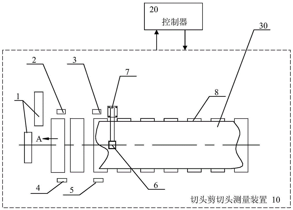
[0048] Such as figure 1 As shown, in order to realize the automation of the cutting head and shearing head in the present invention, in the cutting head and shearing head measuring system used, a set of cutting head measuring device 10 is set before the cutting head shear 1, and the steel plate 30 is measured during operation. The head shape of the steel plate 10 is monitored, and the measured head shape data is transmitted to the controller 20, and the controller 20 controls the start-up time of the cropping shears 1, so that the length of the cutting head reaches the optimum state.

[0049] The cutting head measuring device 10 used in the present invention includes: 2 gratings 2, 3 installed on one side of the roller table 8, wherein the first grating 2 is close to the cutting head ...


PUM


Abstract

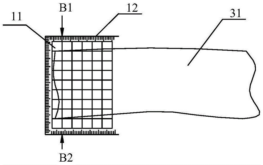
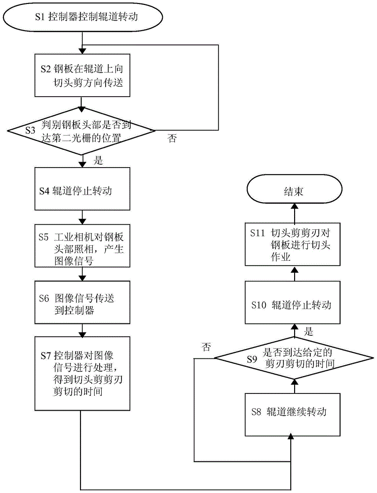
A method for optimizing steel plate head shearing relates to a method of shearing steel plate head, and solves the problem that the existing method cannot precisely locate the portion needs to be sheared; the method comprises the following steps: controlling a roller bed to rotate by a controller in order to transmit a steel plate; controlling the roller bed to stop rotating when the head of the steel plate reaches a second optical grating; using an industrial camera to take a picture of the head of the steel plate, so as to generate a steel plate head image signal and send the signal into the controller; processing the steel plate head image signal by the controller, so as to obtain a shearing time of a head shear blade based on the image signal; keeping the rotation of the roller bed; judging that the shearing time of the head shear blade is reached, stopping the rotation of the roller bed, and stopping the transmission of the steel plate; shearing the head of the steel plate by the head shear blade. In the method, the industrial camera is used for precisely taking a picture of the outline of the steel plate head; by meshing and scanning the image, the length should be sheared from the steel plate head can be precisely calculated, thereby effectively increasing the precision of shearing the steel plate head, thus increasing the shearing efficiency and the yield.

Description

technical field [0001] The invention relates to a steel plate head shearing method of a thick plate production line, in particular to a method for optimizing the steel plate head shearing. Background technique [0002] The shearing line is part of the main line of heavy plate production and is usually the bottleneck of the main production line. The throat of the shearing line is the shearing shear for segmental rough cutting of the rolled slab. The production efficiency and rough cutting rationality of the shearing shear directly affect the efficiency and yield of the entire shearing line. Cutting shears are the first process of the shearing line. They are directly responsible for the finished product and are also the decisive factor in determining the output of thick plates. Therefore, the production efficiency of the cutting shears is directly related to the increase in product output. [0003] At present, a PSG (slab shape detector) is equipped before the shearing line s...

Claims


Application Information

Patent Timeline
Patent Type & Authority Patents(China)
IPC IPC(8): B23D33/00
Inventor 丁海绍刘飞肖湖福孔利明葛国军王科王俊磊
Owner BAOSHAN IRON & STEEL CO LTD
Learn More