
Diffuser, design method of diffuser, manufacturing method of diffuser, display device, projection device, and lighting device

A design method and technology for diffuser plates, applied in the field of diffuser plates, can solve the problems of high production costs, a large amount of time required for comprehensive evaluation of results, and a large amount of data, and achieve the effects of excellent durability and excellent diffusion characteristics.

Active Publication Date: 2021-12-21
DEXERIALS CORP
View PDF9 Cites 0 Cited by
  • Summary
  • Abstract
  • Description
  • Claims
  • Application Information

AI Technical Summary

Problems solved by technology

At this time, when the entire drawing area is not a repeating pattern, there will be a problem that the amount of data becomes huge
Moreover, when evaluating drawing productions, there is also the problem that the production cost becomes high, for example, the evaluation site cannot be narrowed down because the pattern does not repeat, so that it takes a lot of time to comprehensively evaluate the results, etc.

Method used


Image

  • Diffuser, design method of diffuser, manufacturing method of diffuser, display device, projection device, and lighting device
  • Diffuser, design method of diffuser, manufacturing method of diffuser, display device, projection device, and lighting device
  • Diffuser, design method of diffuser, manufacturing method of diffuser, display device, projection device, and lighting device

Examples


no. 1 approach

[0073] (About diffuser plate)

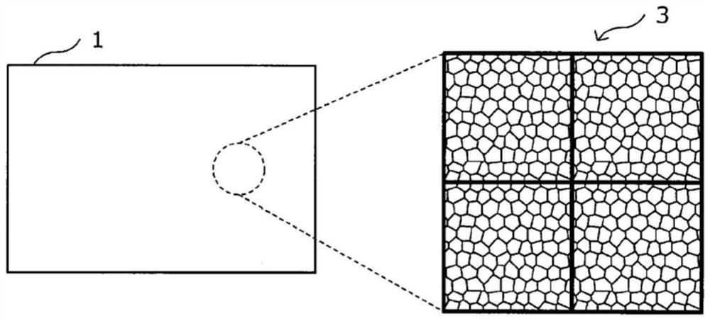
[0074] Below, refer to Figure 1 ~ Figure 7B The diffuser plate 1 according to the first embodiment of the present invention will be described in detail.

[0075] figure 1 It is an explanatory diagram schematically showing the diffusion plate according to the first embodiment of the present invention.

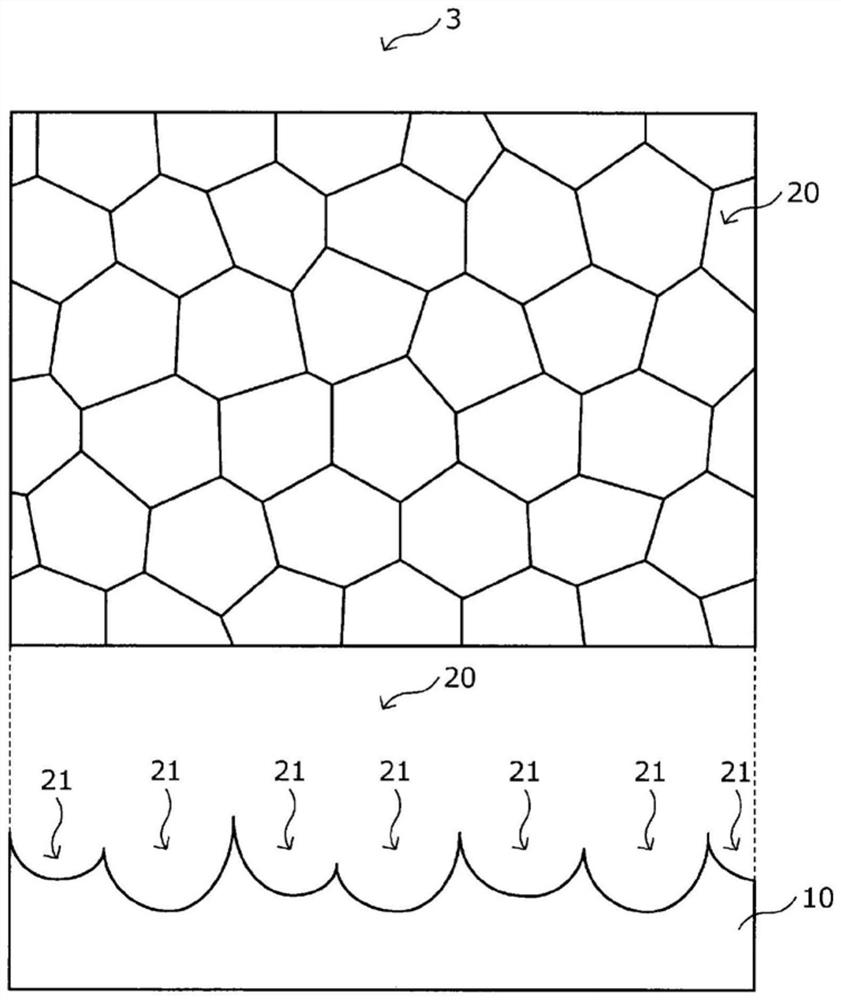
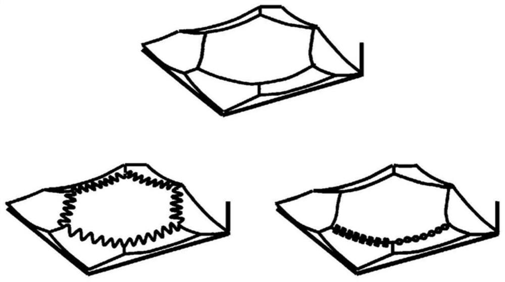
[0076] figure 2 It is an explanatory diagram schematically showing a part of unit cells constituting the diffuser plate according to the present embodiment. Figure 3A ~ Figure 4B It is an explanatory diagram showing an example of the boundary state between adjacent microlenses in the unit cell according to this embodiment. Figure 5 It is an explanatory diagram schematically showing the diffuser plate according to this embodiment. Figure 6A ~ Figure 7B It is an explanatory diagram for explaining the arrangement of unit cells in the diffuser plate according to the present embodiment.

[0077] The diffusion plate 1 according to the present...

no. 2 approach

[0160] As a diffuser for highly coherent light such as laser light, various diffusers having a full angle of diffusion of about 1 degree to 30 degrees are used. For example, in the application of uniformly diffusing the incident laser light with a phosphor surface, a diffusion plate with a full diffusion angle of less than 10 degrees is used, and in the application of obtaining the same diffusion characteristics as the phosphor film by using blue light, and in the application of reducing speckle Then use a diffusion plate with a full diffusion angle of about 10 degrees to 30 degrees. When using a microlens type diffuser plate to realize a diffuser plate having a relatively large full angle of diffusion of 10 degrees to 30 degrees, there is a problem that the attenuation of diffused light is not so sharp in the angle region where the intensity of diffused light is attenuated. .

[0161] Therefore, when realizing a diffuser plate applicable to the above-mentioned application us...


PUM

PropertyMeasurementUnit
lengthaaaaaaaaaa
refractive indexaaaaaaaaaa

Abstract

A diffusion plate that not only exhibits excellent diffusion characteristics but also has excellent durability against highly coherent light is manufactured with high productivity. The diffuser plate involved in the present invention is a microlens array type diffuser plate including a microlens group located on the surface of a transparent substrate. For the plurality of microlenses, the ridges between the adjacent microlenses are not parallel to each other, nor are they parallel to the transparent substrate.

Description

technical field [0001] The present invention relates to a diffuser plate, a design method of the diffuser plate, a manufacturing method of the diffuser plate, a display device, a projection device and an illumination device. Background technique [0002] A diffuser plate for diffusing incident light in various directions is widely used in various devices such as display devices such as monitors, projection devices such as projectors, and various lighting devices. Mechanisms for diffusing incident light in the diffuser are roughly classified into light refraction due to the surface shape of the diffuser and scattering by a substance existing inside the block and having a different refractive index from the surroundings. One of the diffusion plates that utilize light refraction caused by the surface shape is called a microlens array type diffusion plate, which arranges a plurality of microlenses with a size of about several tens of μm on the surface of a block. [0003] In th...

Claims


Application Information

Patent Timeline
Patent Type & Authority Patents(China)
IPC IPC(8): G02B5/02G03B21/20
CPCF21V5/02G02B1/115G02B1/118G02B3/00G02B5/02G03B21/14G09F9/00F21V5/004G02B3/0043G02B5/0221G03B21/625G02B3/0006
Inventor 花岛直树高田昭夫涉谷和幸松野雄介
Owner DEXERIALS CORP
Learn More