
A kind of herringbone gear processing device and its turning and milling method

A processing device and herringbone gear technology, applied in the direction of belts/chains/gears, gear teeth, components with teeth, etc., can solve the problems of low efficiency, large time consumption, and large space occupation, so as to reduce the cost of use, Improved machining accuracy and small floor space

Active Publication Date: 2019-05-24
BAOJI XINFUQUAN MACHINERY TECH DEV
View PDF4 Cites 0 Cited by
  • Summary
  • Abstract
  • Description
  • Claims
  • Application Information

AI Technical Summary

Problems solved by technology

This traditional herringbone gear processing method requires two machine tools, a lathe and a herringbone gear milling machine, to complete the turning and milling of herringbone gears. Due to the need for secondary clamping, there is a secondary clamping error, which affects Gear processing accuracy, and gear transfer and secondary installation need to consume a lot of time, resulting in too much auxiliary time for herringbone gear processing and low efficiency
Therefore, traditional herringbone gear processing requires a lot of equipment, takes up a lot of space, requires a lot of manpower, and consumes a lot of time, and the secondary clamping brings clamping errors
In general, high cost, low efficiency, and poor accuracy

Method used


Image

  • A kind of herringbone gear processing device and its turning and milling method
  • A kind of herringbone gear processing device and its turning and milling method
  • A kind of herringbone gear processing device and its turning and milling method

Examples


Embodiment Construction

[0058] The present invention will be further described in detail below in conjunction with the accompanying drawings, so that those skilled in the art can implement it with reference to the description.

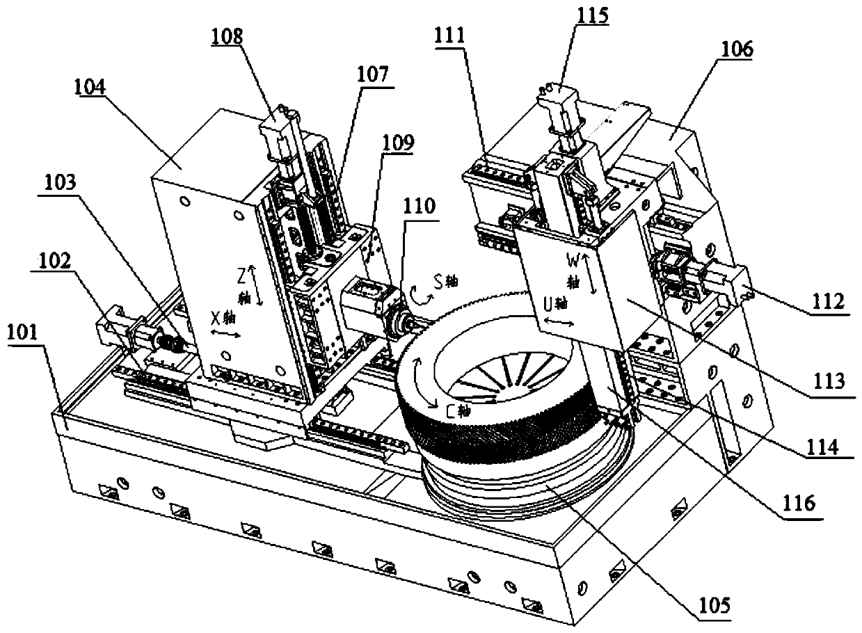
[0059] Such as figure 1 As shown, the present invention provides a herringbone gear processing device, including a main bed 101, which is characterized in that: the left part of the upper end surface of the main bed 101 is installed by a first linear guide 102 and a first ball screw 103 There is a milling column 104 that moves left and right along the X axis, a turning and milling common workbench 105 that rotates around the C axis is installed on the right front of the main bed 101, and a vertical lathe bed is fixed on the right rear of the main bed 101 106; the inner end surface of the milling column 104 is equipped with a milling tool holder 109 moving up and down along the Z axis through the second linear guide rail 107 and the second ball screw 108, and the milling tool ...


PUM


Abstract

The invention discloses a herringbone gear machining device. The herringbone gear machining device comprises a main lathe bed, a tooth milling stand column, a tooth milling blade, a workbench, a vertical lathe bed, a vertical lathe stand column and a turning blade, wherein the tooth milling blade is arranged on the tooth milling stand column in a sliding manner in the axial direction of the toothmilling stand column through a tooth milling tool rest, the workbench is rotationally arranged on the other side of the axial direction of the main lathe bed, the turning blade is arranged in a hollowstructure of the vertical lathe stand column in a sliding manner in the axial direction of the vertical lathe stand column, turning and milling share one rotation workbench, and a herringbone gear can be machined with high precision. The invention discloses a turning method for the herringbone gear machining device. The turning rotation speed, the cutting feed distance and the turning time of a workpiece are controlled on the basis of the BP neural network, and the turning precision is high. The invention further discloses a milling method for the herringbone gear machining device, the rotation speed of the workbench, the axial motion speed of the gear milling blade and the forward and reverse rotation time of the workbench can be accurately controlled, and the herringbone gear machiningprecision is improved.

Description

technical field [0001] The present invention relates to the technical field of gear processing, and more specifically, the present invention relates to a herringbone gear processing device and its turning and milling methods. Background technique [0002] Herringbone gears have the advantages of stable operation, low noise, large bearing capacity, and no axial force. They are widely used in petroleum machinery, engineering machinery, mining machinery, ships and other industries. With the rapid development and technological upgrading of these industries, high The demand for precision herringbone gears is increasing day by day, which puts forward higher requirements for the precision and processing efficiency of herringbone gears. [0003] The traditional herringbone gear processing technology usually clamps the gear blank on the lathe first, turns the outer circle, inner hole and end face of the herringbone gear, and then clamps it on a special herringbone gear milling machin...

Claims


Application Information

Patent Timeline
Patent Type & Authority Patents(China)
IPC IPC(8): B23F7/00
CPCB23F7/00
Inventor 刘天寅赵福长赵新刘明
Owner BAOJI XINFUQUAN MACHINERY TECH DEV
Learn More