
Automatic transporting device for round workpiece milling machine

An automatic conveying device and a technology for circular workpieces, which are applied in metal processing and other directions, can solve problems such as inability to automatically drop, high limitations, and limited pressure-feeding thickness, and achieve smooth dropping process, high degree of automation, and clamping solid effect

Active Publication Date: 2018-08-03
滁州市成业机械制造股份有限公司
View PDF8 Cites 3 Cited by
  • Summary
  • Abstract
  • Description
  • Claims
  • Application Information

AI Technical Summary

Problems solved by technology

[0003] First, the pressure feeding thickness of the two parallel nip rollers is relatively limited, and the intelligently processed rough workpieces have relatively consistent dimensions, but the size of the rough workpiece often leads to transportation difficulties and equipment damage, which directly affects the processing efficiency and the service life of the equipment;
[0004] Second, the pinch roller transport can only send the blank workpiece to the position of the milling cutter, and cannot complete all the operations when the machine is shut down, but must leave a small amount of blank workpieces that cannot meet the needs of subsequent production in the milling machine, resulting in a low product yield;
[0005] Third, when the workpiece is clamped and fixed on the milling machine, the blanks are often fixed one by one manually, which not only wastes manpower, material resources and working time to a certain extent, but also cannot be automatically dropped after the workpiece is processed. fall, higher limitations;

Method used


Image

  • Automatic transporting device for round workpiece milling machine
  • Automatic transporting device for round workpiece milling machine
  • Automatic transporting device for round workpiece milling machine

Examples


Embodiment Construction

[0024] The following will clearly and completely describe the technical solutions in the embodiments of the present invention with reference to the accompanying drawings in the embodiments of the present invention. Obviously, the described embodiments are only some, not all, embodiments of the present invention. Based on the embodiments of the present invention, all other embodiments obtained by persons of ordinary skill in the art without making creative efforts belong to the protection scope of the present invention.

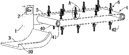
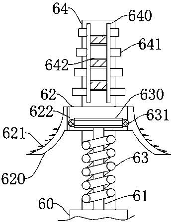
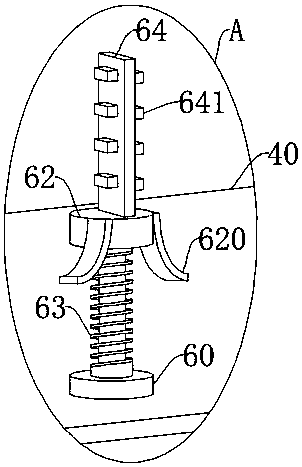
[0025] Such as Figure 1-3 As shown: an automatic conveying device for a circular workpiece milling machine, including a milling machine equipment frame 1, a control terminal 2 and an connecting plate 3 are fixed on the front face of the milling machine equipment frame 1, and a milling machine workbench 5 is fixed on the right end face, and The milling machine table 5 is provided with a transmission device 4 and a clamping device 6, the clamping device 6 is fi...


PUM


Abstract

The invention provides an automatic transporting device for a round workpiece milling machine. According to the automatic transporting device, a joining plate is arranged at the lower end of a conveying device, the width of the joining plate is larger than the width of a transmission device, the height of a fixing baffle is larger than the radius of a round workpiece, and therefore the falling process of the round workpiece is smooth after the round workpiece is machined, and workpiece damage is avoided; and sixteen clamping devices are arranged in the transverse direction of a conveying beltin a manner that every two clamping devices are symmetrical, a limiting plate is in a shape of a one sixth arc, and first limiting blocks are arranged on the limiting plate in a rubber pyramid shape.When the automatic transporting device works, the round workpiece is stably borne, the production requirements are met, four second limiting blocks are arranged in the longitudinal direction of a fixing plate in the manner than the lengths are increased gradually, four rodless cylinders are arranged in the longitudinal direction of the fixing plate and are electrically connected with a control terminal; and the workpiece can be stably clamped through the device, and the automatic degree is high.

Description

technical field [0001] The invention relates to the related technical field of milling machine workpiece conveying, in particular to an automatic conveying device for a circular workpiece milling machine. Background technique [0002] A milling machine is a machine tool that uses a milling cutter to mill a workpiece. It mainly refers to a machine tool that uses a milling cutter to process various surfaces on a workpiece. Usually, the rotation of the milling cutter is the main movement, and the movement of the workpiece and the milling cutter is the feed movement. It can process planes and grooves, and can also process various curved surfaces, gears, etc. It can be said that milling machine is a machine tool with a wide range of uses. The milling machine can process planes, grooves, toothed parts, spiral surfaces and various curved surfaces. In addition, it can also be used to process and cut off the surface and inner holes of the rotating body. When the milling machine is w...

Claims


Application Information

Patent Timeline
Patent Type & Authority Applications(China)
IPC IPC(8): B23Q7/00
CPCB23Q7/003
Inventor 张志
Owner 滁州市成业机械制造股份有限公司
Learn More