Angle adjusting device and silk-screen printing device

An angle adjustment device and angle technology, applied in printing, printing machine, printing process and other directions, can solve the problems of complex linkage relationship, inability to realize fine control of printing screen frame, etc., to reduce energy consumption, improve transmission efficiency and precision, The effect of improving accuracy and control accuracy

Inactive Publication Date: 2018-08-03
SUZHOU MAXWELL TECH CO LTD
View PDF10 Cites 3 Cited by
  • Summary
  • Abstract
  • Description
  • Claims
  • Application Information

AI Technical Summary

Problems solved by technology

The linkage relationship between these two driving methods is complicated, and it is impossible to achieve fine control of the printing

Method used


Image

  • Angle adjusting device and silk-screen printing device
  • Angle adjusting device and silk-screen printing device
  • Angle adjusting device and silk-screen printing device

Examples


Embodiment Construction

[0030] The present invention can be further clearly understood through the specific examples of the present invention given below, but they are not intended to limit the present invention.

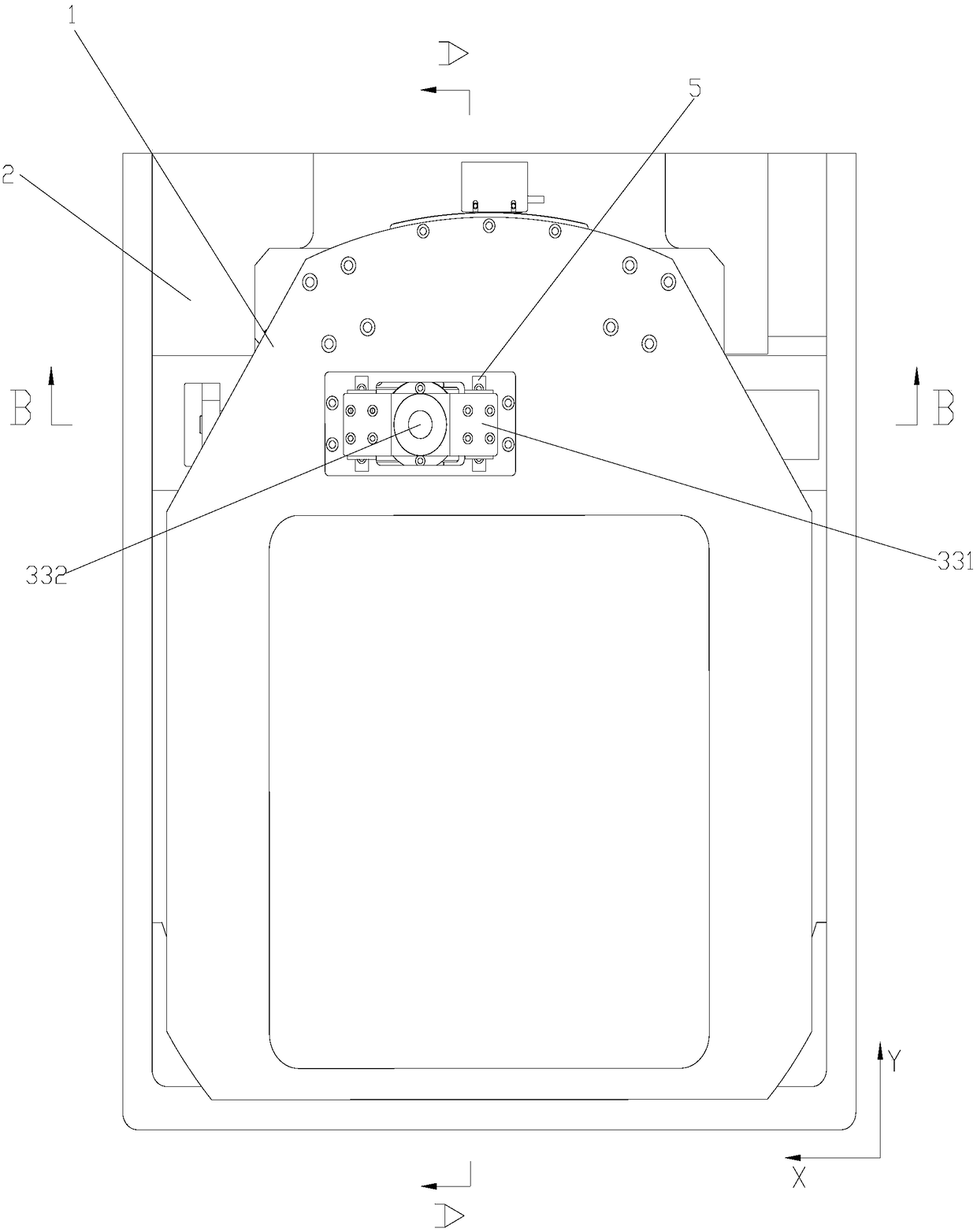
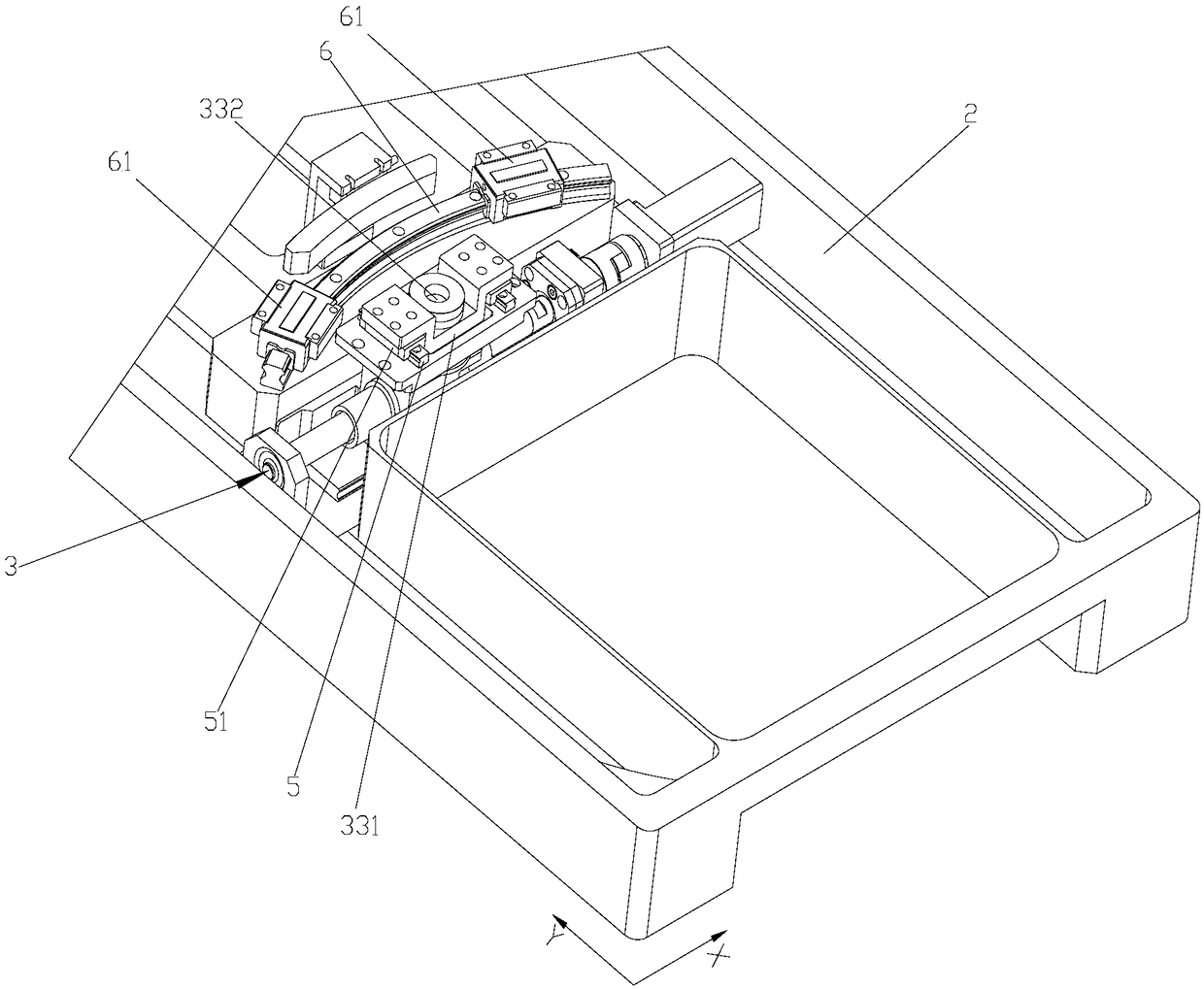
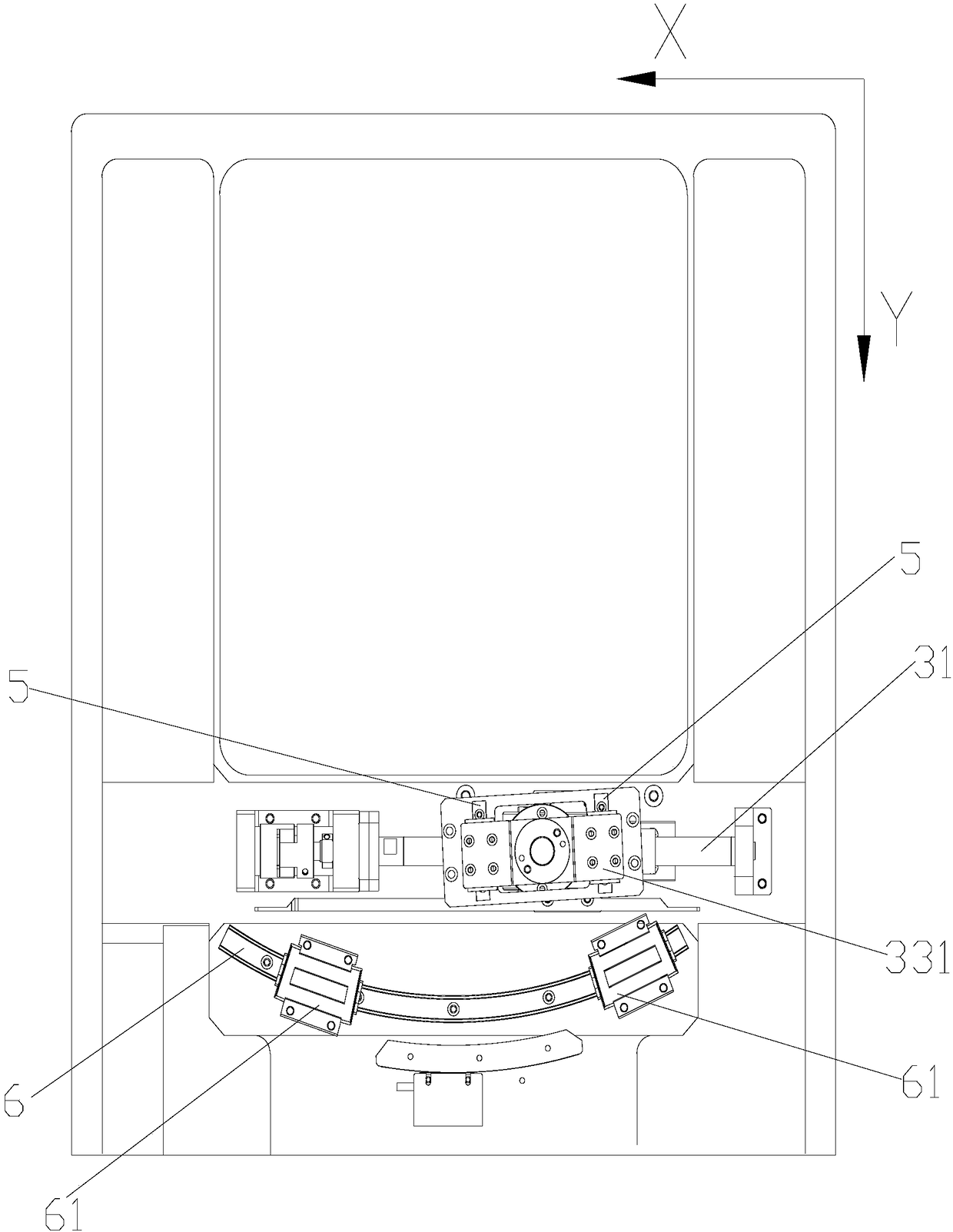
[0031] Such as Figure 1-6 As shown, this embodiment provides an angle adjustment device, which includes a base 2 and an angle running part 1. The base 2 is provided with an arc-shaped guide rail 6, and the angle running part 1 is slidably arranged on the On the arc-shaped guide rail 6, the drive mechanism includes a power device arranged on the base 2, a linear guide rod 31 arranged on the base 2, and a driver 32 slidingly arranged on the linear guide rod 31, the power device For driving the driving member 32 to move along the linear guide rod 31, the driving mechanism 3 also includes a driving connecting member 33, which is rotatably connected to the driving member 32, and the driving connecting member 33 is fixed on the angle running member 1 along the The linear guide device 5 is mova...


PUM


Abstract

The invention relates to an angle adjusting device which comprises a base and an angle operating piece. An arc-shaped guide rail is arranged on the base, and the angle operating piece is slidably arranged on the arc-shaped guide rail under driving of a driving mechanism. The driving mechanism comprises a linear guide rod arranged on the base, a driving piece slidably arranged on the linear guide rod, and a power device for driving the driving piece to move in the length direction of the linear guide rod. The driving mechanism further comprises a driving connecting piece which is rotatably connected with the driving piece and movably connected with the angle operating piece along a linear guiding device fixedly arranged on the angle operating piece. The angle adjusting device decomposes thecomplex linkage relation between the driving piece, making simple linear movement, inside the driving mechanism and the angle operating piece making arc-shaped movement into two types of movement components which are easier to control, and accordingly, the angle precision and control precision are improved.

Description

technical field [0001] The invention relates to a printing device, in particular to an angle adjustment device and a printing screen device used in the manufacture of monocrystalline silicon and polycrystalline silicon solar cells. Background technique [0002] In order to print the motor on the front side of the silicon wafer, after the silicon wafer is positioned on the workbench, the position of the silver grid line needs to be adjusted. A method of double-overprinting the front motor has become popular in the industry. In order to ensure that the offset between the two printing overprints is preferably less than 1 micron, at present, the industry has adopted a set of arc-shaped guide rails, grating rulers, and reading heads that cooperate with each other, and the use of radius magnification improves the accuracy of measurement and control. [0003] However, in this prior art, the driving of the arc-shaped guide rail is realized by connecting the driving connecting rod wi...

Claims


Application Information

Patent Timeline
IPC IPC(8): B41F15/08B41F15/36
CPCB41F15/0818B41F15/36B41P2215/112B41P2215/50
Inventor 施政辉陆瑜
Owner SUZHOU MAXWELL TECH CO LTD
Why Eureka
Try Eureka