Automatic inserting-extracting type new energy car charging pile capable of being accurately lifted

A new energy vehicle, automatic plugging and unplugging technology, applied in the direction of electric vehicle charging technology, electric vehicles, charging stations, etc., can solve problems such as electric shock to the human body, and achieve the effects of convenient control, easy plugging and unplugging, and simple operation.

Inactive Publication Date: 2018-08-03
郑州恒之博新能源科技有限公司
View PDF1 Cites 11 Cited by
  • Summary
  • Abstract
  • Description
  • Claims
  • Application Information

AI Technical Summary

Problems solved by technology

[0006] The invention overcomes the deficiencies of the prior art, provides a charging pile for new energy vehicles that can be automatically plugged and unplugged to avoid electric shock to the human body, and solves the problem that the existing new energy vehicles need to hold the gun body to charge and cause electric shock to the human body

Method used


Image

  • Automatic inserting-extracting type new energy car charging pile capable of being accurately lifted
  • Automatic inserting-extracting type new energy car charging pile capable of being accurately lifted

Examples


Embodiment 1

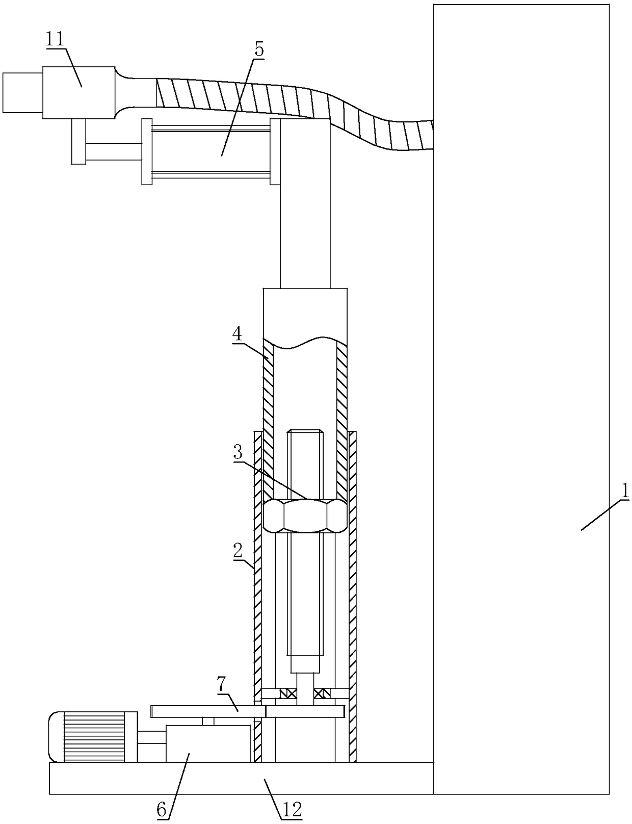
[0023] The automatic plug-in new energy vehicle charging pile that can be lifted accurately includes a charging pile main body 1, a charging plug 11 is connected to the charging pile main body 1; a mounting plate 12 is connected to the charging pile main body 1, and a mounting plate 12 is fixed on the charging pile body Sleeve 2, lead screw and nut mechanism 3 is connected inside the casing 2, the other end of lead screw and nut mechanism 3 is connected with lift tube 4, the other end of lift tube 4 is connected with cylinder 5, the piston rod of cylinder 5 and charging plug 11 Fixedly connected; the drive mechanism 6 is also installed on the mounting plate 12, the output shaft of the drive mechanism 6 is connected with the transmission mechanism 7, and the output end of the transmission mechanism 7 is connected with the screw nut mechanism 3.

[0024] The driving mechanism 6 of the present invention can drive the transmission mechanism 7 to act, and the transmission mechanism ...

Embodiment 2

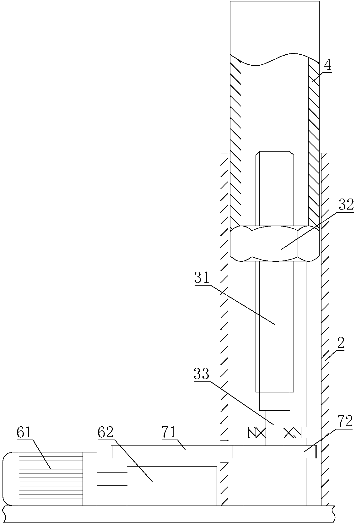
[0026] On the basis of Embodiment 1, the lead screw nut mechanism 3 includes a lead screw 31, the lead screw 31 is sleeved in the casing 2, the lead screw 31 is threadedly connected with a nut 32, and the lifting tube 4 is fixed on the nut 32; One end of bar 31 is connected with connecting shaft 33, and connecting shaft 33 is connected in the sleeve pipe 2 by bearing, and the other end of connecting shaft 33 is connected with transmission mechanism 7; The shape of the inner ring of the section of sleeve pipe 2 is polygonal.

[0027] When the transmission mechanism 7 drives the lead screw 31 to rotate, the rotation of the nut 32 is restricted by the sleeve 2, and the nut 32 rises and falls linearly under the drive of the lead screw 31, and the lifting tube 4 and the cylinder rise and fall under the push of the nut 32, so that the charging plug 11 can Reliable lifting. The lead screw nut mechanism 3 has a certain transmission ratio, and the lifting distance of the charging plug ...

Embodiment 3

[0029] On the basis of Embodiment 1 or Embodiment 2, the drive mechanism 6 includes a motor 61, the output shaft of the motor 61 is connected with a speed reducer 62, the motor 61 and the speed reducer 62 are all installed on the mounting plate 12, and the speed reducer 62 The output shaft is connected with the input end of the transmission mechanism 7 .

[0030] After the motor 61 starts, the motor 61 drives the speed reducer 62 to act, and the speed reducer 62 transmits the power to the transmission mechanism 7, so the transmission mechanism 7 can drive the lead screw and nut mechanism 3 to act. The present invention is driven by the motor 61, and the starting time of the motor 61 determines the lifting height of the charging plug 11, and the turning direction of the motor 61 determines the moving direction of the charging plug 11, which is convenient to control and easy to operate.


PUM


Abstract

The invention relates to the field of new energy car charging piles, in particular to an automatic inserting-extracting type new energy car charging pile capable of being accurately lifted. Accordingto the technical scheme, the automatic inserting-extracting type new energy car charging pile capable of being accurately lifted comprises a charging pile body, a charging plug is connected with the charging pile body; an installation plate is connected with the charging pile body and is fixed with a casing pipe, a screw rod nut mechanism is connected into the casing pipe, a lifting pipe is connected with the other end of the screw rod nut mechanism, an air cylinder is connected with the other end of the lifting pipe, and a piston rod of the air cylinder is fixedly connected with the chargingplug; a driving mechanism is further arranged on the installation plate, an output shaft of the driving mechanism is connected with a transmitting mechanism and the screw rod nut mechanism is connected with the output end of the transmitting mechanism. The automatic inserting-extracting type new energy car charging pile capable of being accurately lifted solves the problem that the new energy carneeds a handheld gun body to charge thus causing the electric shock to the human body.

Description

technical field [0001] The invention relates to the field of new energy vehicle charging piles, in particular to an automatic plug-in and pull-out new energy vehicle charging pile that can be lifted and lowered accurately. Background technique [0002] The function of the charging pile is similar to the refueling machine in the gas station. It can be fixed on the ground or wall, and installed in public buildings (public buildings, shopping malls, public parking lots, etc.) and residential area parking lots or charging stations. Charge all models of electric vehicles. The input end of the charging pile is directly connected to the AC grid, and the output end is equipped with a charging plug for charging the electric vehicle. Charging piles generally provide two charging methods: conventional charging and fast charging. People can use a specific charging card to swipe the card on the human-computer interaction interface provided by the charging pile to perform corresponding c...

Claims


Application Information

Patent Timeline
Patent Type & Authority Applications(China)
IPC IPC(8): B60L11/18
CPCB60L53/16B60L53/31B60L53/35Y02T10/70Y02T10/7072Y02T90/12Y02T90/14
Inventor 曾皓
Owner 郑州恒之博新能源科技有限公司
Why Eureka
Try Eureka