
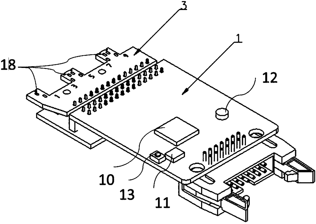
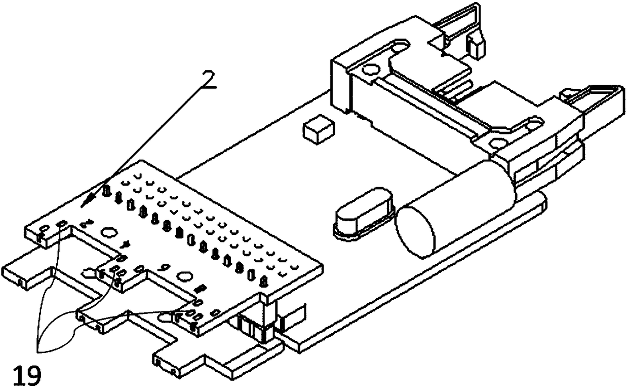
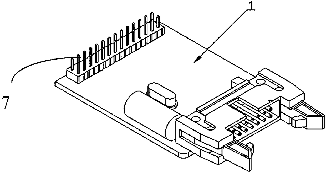
Knitting machine electromagnetic needle selection machine drive plate and knitting machine electromagnetic needle selection machine

A knitting machine and needle selector technology, which is applied in the directions of knitting, weft knitting, textile and paper making, etc., can solve the problems of low integration, inconvenient installation time, low safety of electricity consumption, etc. Installation, small footprint effect

Active Publication Date: 2018-08-03
HANGZHOU XUREN TEXTILE MACHINERY
View PDF6 Cites 0 Cited by
  • Summary
  • Abstract
  • Description
  • Claims
  • Application Information

AI Technical Summary

Problems solved by technology

However, it is very difficult to change the number of the drive plate of the electromagnetic needle selector of the existing knitting machine. Because the interval between the electromagnetic needle selectors on the knitting machine is small, a series of steps such as dismantling the cam seat are required, the labor efficiency is low, and the maintainability is poor.
Furthermore, the driving board of the electromagnetic needle selector of the knitting machine is connected with the electromagnetic induction coil in the form of a plug-in. This connection method is time-consuming and inconvenient to install, and it is very easy to cause a short circuit during manual live operation, and the safety of electricity is low. Weak anti-interference ability and low integration

Method used


Image

  • Knitting machine electromagnetic needle selection machine drive plate and knitting machine electromagnetic needle selection machine
  • Knitting machine electromagnetic needle selection machine drive plate and knitting machine electromagnetic needle selection machine
  • Knitting machine electromagnetic needle selection machine drive plate and knitting machine electromagnetic needle selection machine

Examples


Embodiment Construction

[0025] The specific implementation manners of the present invention will be further described in detail below in conjunction with the accompanying drawings and embodiments. The following examples are used to illustrate the present invention, but are not intended to limit the scope of the present invention.

[0026] The inventor has tried to change the serial number of the electromagnetic needle selector by means of binary address dialing, but this method needs to be manually changed on the driving board of the electromagnetic needle selector of the knitting machine, which is easy to dial wrongly or not in place, and the electromagnetic needle selector on the knitting machine The installation interval between the devices is small, the binary address dial module and other modules on the driving board of the electromagnetic needle selector of the knitting machine are close to each other, the dial space is very limited, and the dial operation is easily hindered, while the electroma...


PUM


Abstract

The invention provides a knitting machine electromagnetic needle selection machine drive plate and a knitting machine electromagnetic needle selection machine. The knitting machine electromagnetic needle selection machine drive plate comprises a processor module, an address button module, a receiving and dispatching module, an output module and a power module. The address button module is electrically connected with the processor module to change the number of the knitting machine electromagnetic needle selection machine drive plate through buttons; the knitting machine electromagnetic needleselection machine comprises an electromagnetic coil, the knitting machine electromagnetic needle selection machine drive plate, a first adapter plate and a second adapter plate; the electromagnetic coil is provided with two ends; the first adapter plate is connected with the knitting machine electromagnetic needle selection machine drive plate; the second adapter plate is connected with the firstadapter plate; the first adapter plate and the second adapter plate are respectively connected with the two ends of the electromagnetic coil. The knitting machine electromagnetic needle selection machine drive plate can simply and efficiently change the numbers, and the integration level of the knitting machine electromagnetic needle selection machine is higher.

Description

technical field [0001] The invention relates to the technical field of numerical control of knitting machines, in particular to a drive plate of an electromagnetic needle selector of a knitting machine and an electromagnetic needle selector of a knitting machine. Background technique [0002] The needle selector of the knitting machine is the core component in the knitting machine. The electromagnetic needle selector of the knitting machine is generally composed of four parts: the drive plate of the electromagnetic needle selector of the knitting machine, the magnetic rod, the electromagnetic induction coil, and the cutter head of the electromagnetic needle selector. The electromagnetic needle selector of knitting machine uses currents in different directions to the electromagnetic induction coil to make the polarity of the electromagnetic induction coil change accordingly, or it is used in conjunction with a magnetic rod to realize electromagnetic needle selection by the at...

Claims


Application Information

Patent Timeline
Patent Type & Authority Applications(China)
IPC IPC(8): D04B15/66
CPCD04B15/66D04B15/665
Inventor 彭来湖王罗俊戴宁胡旭东未印吕明来牛冲沈春娅周佳超李建强
Owner HANGZHOU XUREN TEXTILE MACHINERY
Learn More