Vibration damping device

A vibration damping and end cap technology, applied in the field of vibration damping, can solve the problem of easy fatigue failure of elastic components, and achieve the effects of increased excitation force, convenient processing and assembly, and improved fatigue strength and bearing capacity.

Inactive Publication Date: 2018-08-03
ZHUZHOU TIMES NEW MATERIALS TECH
View PDF5 Cites 4 Cited by
  • Summary
  • Abstract
  • Description
  • Claims
  • Application Information

AI Technical Summary

Problems solved by technology

At present, vibration damping devices widely used in engineering h

Method used


Image

  • Vibration damping device

Examples


Embodiment Construction

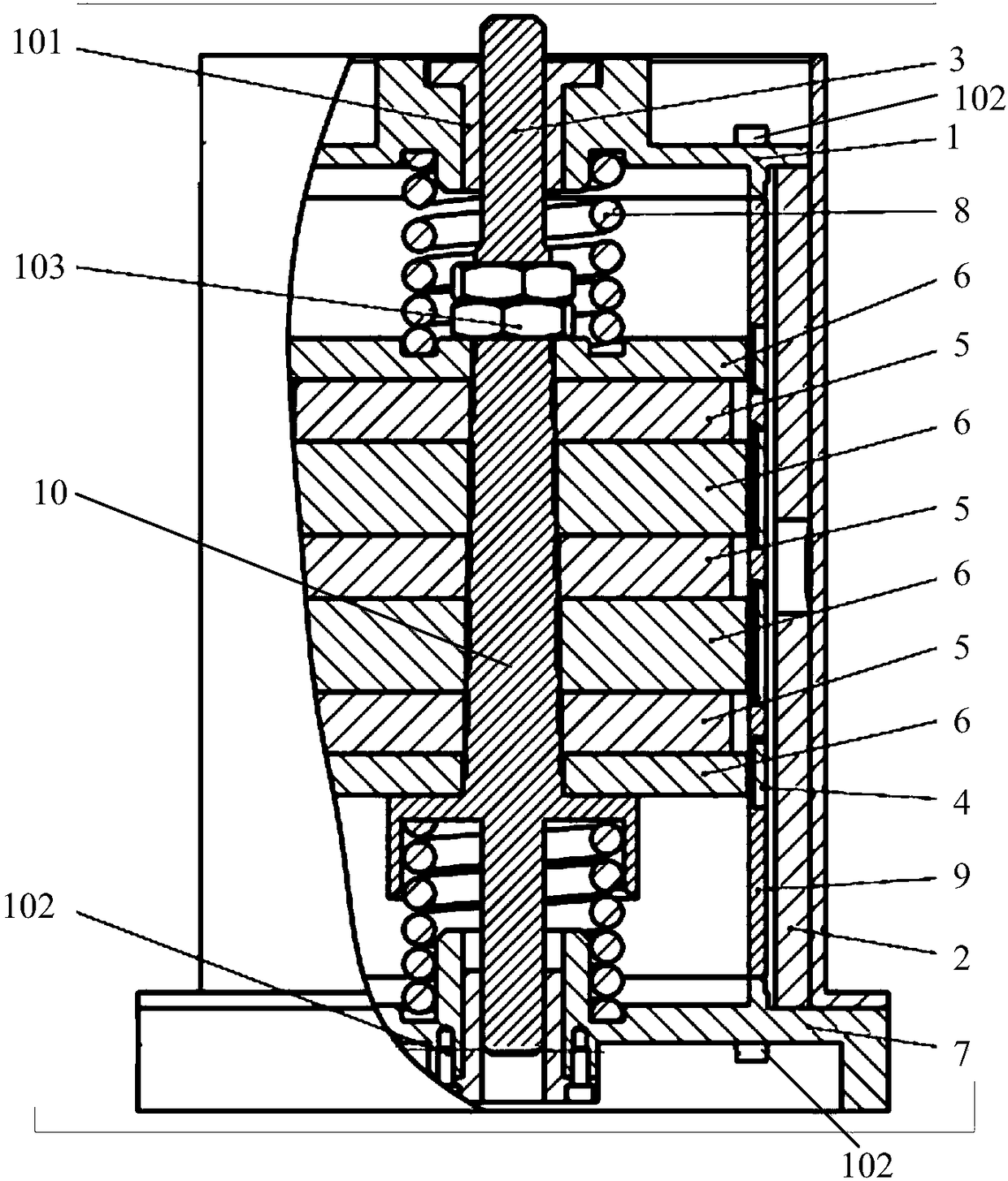
[0016] The present invention will be further described in detail below in conjunction with the accompanying drawings and specific embodiments, but the protection scope of the present invention is not limited thereby.

[0017] figure 1 The overall cross-sectional structure of the vibration damping device 10 according to the embodiment of the present invention is schematically shown. like figure 1 As shown, the vibration damping device 10 of the embodiment of the present invention includes an end cover 1 , a housing 2 , a main shaft 3 , a coil 4 , a permanent magnet 5 , a magnetic guide plate 6 , a base 7 and a cylindrical spring 8 . The main shaft 3 is located in the housing 2, the permanent magnets 5 and the magnetic plates 6 are alternately sleeved on the main shaft 3, the adjacent permanent magnets 5 are oppositely arranged with the same pole, and the upper and lower sides of the permanent magnets 5 are provided with the magnetic plates 6. The coil 4 is arranged opposite t...


PUM


Abstract

The invention provides a vibration damping device which comprises an end cover, an outer shell, a main shaft, coils, permanent magnets, magnetic conductive plates, a base and cylindrical springs, wherein the main shaft is positioned in the outer shell; the permanent magnets and the magnetic conductive plates alternately sleeve the main shaft; the same poles of the adjacent permanent magnets are oppositely arranged; the magnetic conductive plates are arranged on both the upper and lower sides of the permanent magnets; the coils and the magnetic conductive plates are oppositely arranged; throughthe winding direction or the wiring design of the coils, the current flow directions of any two adjacent coils can be opposite; the coils are fixed in the outer shell; two ends of the main shaft arecorrespondingly fixed on the end cover and the base; one cylindrical spring is arranged between the end cover and the magnetic conductive plate which is close to the end cover; and the other cylindrical spring is arranged between the base and the magnetic conductive plate which is close to the base. The fatigue strength and the carrying capacity of the whole vibration damping device can be improved, and then the working life of the vibration damping device can be prolonged.

Description

technical field [0001] The invention relates to the technical field of vibration reduction, in particular to a vibration reduction device. Background technique [0002] Vibration control can be divided into passive vibration control and active vibration control from the perspective of external energy demand. Vibration passive control is also known as passive control. Its technology is simple and easy to implement, and it has good economy and reliability. It is widely used in the field of vibration control, but it only has a good control effect on high frequencies. Therefore, active vibration control, that is, active vibration control, becomes particularly important. Because it can adapt to the change of external disturbance frequency and has a good control effect on low frequencies, it has become a new hot spot in the field of vibration engineering. In the active control of vibration, the actuator is one of the key technologies, and the most common method is to install a vi...

Claims


Application Information

Patent Timeline
IPC IPC(8): F16F7/00F16F6/00
CPCF16F7/00F16F6/00F16F2238/026
Inventor 唐振国周常荣涂奉臣王里达
Owner ZHUZHOU TIMES NEW MATERIALS TECH
Why Eureka
Try Eureka